Tank Plumbing System Design: Inlet, Outlet, Vent, Overflow, Drain Tie-In Walkthrough


The tank shell is the cheapest and easiest part of a working storage system. The plumbing — inlet, outlet, vent, overflow, drain, level instrumentation, and the gasket-and-fastener stack at every penetration — is where most installations fail. A correctly-specified Norwesco, Snyder, Chem-Tainer, Enduraplas, or Bushman tank installed with under-sized bulkheads, missing vent capacity, an overflow that re-enters the same containment, or an EPDM gasket on petroleum service will leak, vacuum-collapse, or fail compliance audit inside a year. This pillar walks each penetration in order so you can plumb a tank correctly the first time.
The reference codes in this guide are ASTM D1998 Section 8 (fittings, support, and venting), the International Plumbing Code (IPC) Chapter 6 (water supply and distribution), Uniform Plumbing Code (UPC) Chapters 6 and 7, NFPA 30 Chapter 21 for petroleum service, NSF/ANSI 61 for potable, and the manufacturer fitting-installation manuals from Snyder, Norwesco, and Banjo. We cite real bulkhead and fitting SKUs from the OneSource Plastics catalog, including Snyder MPN 34100053 (4-inch PP threaded bulkhead with EPDM gasket), MPN 34200179 (1-inch PVC socket-by-thread bulkhead), MPN 34400338 (1-1/2-inch CPVC threaded with EPDM), MPN 34700436 (1-1/2-inch double-flanged CPVC with Viton and stainless encapsulated washers), and MPN 34700889 (6-inch double-flanged CPVC bolted with Viton and Hastelloy hardware).
The Six-Penetration Tank: What You Must Plumb
- Inlet (top fill): the line that fills the tank. Top inlet is the safe default; side or bottom inlet is acceptable for specific service.
- Outlet (suction or gravity): the line that delivers liquid to the system. Located at the lowest point that allows full draw without sediment lift.
- Vent: the atmosphere-equalization port. Without it, fast-fill creates pressure and fast-draw creates vacuum collapse. Sized larger than the maximum fill or draw rate.
- Overflow: the high-water failsafe that diverts excess fluid to a safe location when the inlet runs past the design fill volume.
- Drain (cleanout): the low-point port for tank flushing, sediment removal, or end-of-life drain-down.
- Level instrumentation port: for level switch, level transmitter, sight-glass, or visual stick gauge.
A minimum compliant water tank installation has all six. Skipping the vent or undersizing the overflow is the most common failure pattern.
Penetration #1: The Inlet
Top inlet: the default
Top fill drops fluid from the inlet pipe through the tank headspace into the body. Advantages: simple, no backflow risk into the supply line, splash mixing assists temperature equalization. Disadvantages: surface foaming on detergents and surfactants, potential for vortex air entrainment on rapid drain, splash erosion on the bottom for unprotected fill drops.
Specification rules:
- Inlet pipe inside diameter at least equal to the supply pipe ID. Reducing creates pressure drop and slows fill.
- For tanks above 1,500 gallons, install a fill diffuser or stilling tube to reduce splash and air entrainment.
- Provide a drop loop or air gap at the inlet per IPC 608.13 to prevent backflow into the potable supply.
- Use a fitting rated for the chemistry: NSF 61 for potable, polypropylene or CPVC for chemistry.
Bulkhead-mounted side inlet: the alternative
Side inlet through a bulkhead fitting is acceptable when piping geometry forces it. Use a check valve in the supply line to prevent reverse-siphon from the tank into the supply, and locate the side inlet above the design high-water line so the fitting is never submerged when the tank is at design volume.
Penetration #2: The Outlet
Bottom outlet
Bottom outlet is the standard for vertical tanks under approximately 5,000 gallons. The bulkhead penetrates the lower sidewall close to the floor. Specify the outlet diameter to match the maximum design draw rate without exceeding 7-10 feet per second pipe velocity (above which water-hammer and noise become problematic).
- Standard outlet sizes: 1 inch for tanks under 500 gallon, 1-1/2 to 2 inch for 500-3,000 gallon, 2 to 3 inch for 3,000-5,000 gallon, 3 to 4 inch for above. Snyder MPN 34100053 covers the 4-inch class; MPN 34400338 covers the 1-1/2 inch class.
- Outlet height: bottom outlet sits 2-4 inches above the floor on most factory tanks to leave a sediment trap below the line. This is intentional; it keeps grit and biofilm out of the suction.
- Suction-side accessory: always install a manual ball valve at the bulkhead so you can isolate the tank from downstream piping for service.
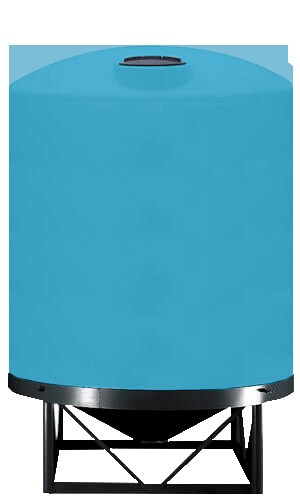
- Cone-bottom tanks: the cone outlet drains the entire contents including sediment. Required when the chemistry settles solids (lime slurry, algae feedstock, polymer-conditioned wastewater).
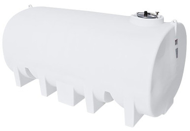
Side outlet with gravity head
Side outlets are common on agricultural and water-haul service where a gravity-fed system pulls from the upper tank section. Calculate static head as height of fluid above the outlet centerline times specific gravity of the fluid in psi: head_psi = height_ft × 0.433 × SG.
Penetration #3: The Vent — Most Critical and Most Misunderstood
The vent equalizes pressure between tank headspace and atmosphere. When the tank fills, displaced air must escape; when fluid is drawn out, replacement air must enter. Insufficient vent capacity produces two failure modes:
- Pressure failure on fill: rapid fill creates internal pressure that bulges or splits the tank top. Polyethylene rotomolded tanks are atmospheric vessels — even 1-2 psi of internal pressure exceeds design.
- Vacuum collapse on draw: rapid pump-out without sufficient vent capacity creates negative pressure that implodes the tank wall. Catastrophic and irreversible. Most common failure mode on pump-fed wash bays, fire-suppression draw tests, and fuel-truck loading.
Vent sizing rule of thumb
The classic field rule: vent area at minimum equal to the largest of (a) inlet pipe area, (b) outlet pipe area, (c) the maximum fill or draw rate equivalent. For most tanks under 5,000 gallons on water service this means a 4-inch atmospheric vent or larger. NFPA 30 Section 21.4.3 provides the explicit formulas for petroleum service and is the binding code for fuel storage; ASTM D1998 Section 8.2 provides the polyethylene-tank guidance for general chemistry.
| Tank Capacity | Min Atmospheric Vent (water) | Min Vent (petroleum, NFPA 30) | Notes |
|---|---|---|---|
| Under 500 gallon | 2 inch | 2 inch + emergency vent | Lid vent acceptable for low fill rate |
| 500 - 1,500 gallon | 3 inch | 3 inch + emergency vent | Bulkhead vent or vented manway |
| 1,500 - 5,000 gallon | 4 inch | 4 inch + emergency vent | Vented manway lid is industry standard |
| 5,000 - 12,000 gallon | 6 inch | 6 inch + emergency vent | Engineered vent system required |
| Above 12,000 gallon | Engineered | Engineered | Pressure / vacuum vent valve required |
OneSource stocks vented lid hardware in standard 14- and 16-inch manway sizes; representative SKUs include MPN 63485 (16-inch lid and ring with snap-in vent) and MPN 34701295 (14-inch threaded non-vented manway, paired with a separate atmospheric vent bulkhead).
Vent placement rules
- Vent goes at the highest point of the tank top.
- Atmospheric vent terminates with a screen (insect / debris exclusion) and a turn-down or weather cap to keep rainwater out.
- Petroleum service requires a separate emergency vent device sized to relieve fire-exposure pressurization per NFPA 30 Section 21.4.3.
- Do not connect multiple tanks to a common vent header without a vacuum breaker on each — vacuum on one tank can collapse another.
Penetration #4: The Overflow
The overflow is the failsafe that diverts liquid to a safe destination when the fill source overruns the inlet shutoff. On unattended fill systems (rainwater catchment, level-control valve fills, manual-fill water haul) the overflow may discharge regularly and must be plumbed to a code-approved destination.
Overflow sizing
The overflow must be at least one pipe size larger than the inlet, with adequate freeboard between the overflow centerline and the tank top. IPC 608.16.4 requires a minimum 4-inch air gap between the overflow termination and the receiving fixture or grade.
Overflow destination
- Water tanks: overflow discharges to surface drainage, dry well, or ground a safe distance from the tank foundation. Never plumb water-tank overflow back into the tank or into a closed sump where it can reverse-siphon.
- Chemistry tanks: overflow must discharge into the secondary containment. Never to ground.
- Petroleum tanks: overflow must terminate inside the secondary containment (dike or double-wall annulus) per NFPA 30 and SPCC 40 CFR 112.
- Septic tanks: overflow indicates system failure; plumb to high-level alarm rather than discharge to ground.
The most common overflow failure mode we see in field service is overflow piped back into the same tank's secondary containment with no high-level alarm. The containment fills silently until inspection finds it months later.
Penetration #5: The Drain (Cleanout)
The drain is the bottom-most port that allows full evacuation of the tank for cleaning, end-of-life decommissioning, or chemistry change-out. On flat-bottom tanks, the drain sits at the floor level and may double as the suction outlet (with appropriate valve switching). On cone-bottom tanks, the cone discharge is the natural drain point.
- Sizing: at minimum equal to the suction outlet; oversize one nominal size for sediment-laden service.
- Hardware: manual ball valve plus removable cap or quick-disconnect. The cap is critical — a leaking valve plus exposed open drain is a slow leak that can run undetected.
- Materials: match the chemistry rating of the rest of the system. Polypropylene for general chemistry, CPVC for hot or aggressive service, stainless for high-temperature or food-grade.
Penetration #6: Level Instrumentation
Visual / mechanical level options
- Sight tube: external clear tube tied to top and bottom bulkheads. Cheap, no power, susceptible to algae and freeze damage. Acceptable for indoor or freeze-protected service.
- Mechanical float gauge with stick indicator: standard on bulk fertilizer, fuel, and water transport tanks.
- Hydrostatic dipstick: a calibrated rod inserted through the manway. Cheap and reliable for daily check.
Electronic level
- Float switches: low-cost level alarm; install one for high level (overflow alarm) and one for low level (pump dry-run protection).
- Pressure transducer: reads hydrostatic head at the bottom; converts to level via fluid SG. Standard for SCADA-tied bulk storage.
- Ultrasonic level: non-contact sensor mounted in the top of the tank. Excellent for chemistry where contact is not desired.
- Radar level: top-of-tank sensor for high-accuracy / inventory-management service. Higher cost.
Instrumentation port should be a separate bulkhead — do not share with vent or overflow because both can drop debris on the sensor.
Bulkhead Fitting Selection: The Gasket Matrix
The bulkhead fitting is the actual sealed penetration through the tank wall. Three pieces matter: the bulkhead body material, the gasket material, and the hardware (washer, nut, bolt) material. Mismatch any of the three and the fitting leaks within months.
Body material decision
| Service | Bulkhead Body | Why |
|---|---|---|
| Potable water (NSF 61) | PVC NSF 61 | Listed for potable; lowest cost |
| Agricultural / general water | PVC or polypropylene | Either works; PP slightly more chemistry-tolerant |
| Sodium hypochlorite 12.5% | CPVC or PP with Viton | Bleach attacks PVC plasticizer; CPVC stable |
| Sulfuric acid concentrated | PVDF or CPVC | PVC fails on concentrated acids |
| Caustic 50% NaOH | PP or CPVC | Excellent chemistry stability |
| Diesel / petroleum | PP or steel | PVC swells in petroleum |
| DEF (urea 32.5%) | PP NSF 61 or stainless | Avoids contamination of urea |
Gasket material decision
| Service | Gasket | Avoid |
|---|---|---|
| Potable / general water | EPDM (NSF 61) | Buna-N (taste / odor) |
| Sodium hypochlorite | Viton (FKM) | EPDM survives but Viton lasts longer |
| Petroleum / diesel | Viton (FKM) or Buna-N | EPDM (swells, fails) |
| Caustic concentrated | EPDM or Viton | Buna-N (degrades) |
| Concentrated acids | Viton or PTFE | EPDM, Buna-N |
| Hot service above 200F | PTFE or specialty | Most elastomers |
Snyder catalog SKUs document the standard-pairing logic clearly: MPN 34100053 ships PP body with EPDM gasket (water and mild chemistry); MPN 34700436 ships CPVC body with Viton gasket and stainless encapsulated washers (aggressive chemistry); MPN 34700889 ships CPVC body with Viton gasket and Hastelloy hardware (extreme chemistry where carbon steel hardware corrodes).
Hardware (washer / bolt) material
- Galvanized steel: water service only. Corrodes on chemistry.
- Stainless steel 304: general service. Avoid on concentrated chlorides (pitting risk).
- Stainless steel 316: chloride-tolerant; default for bleach and saltwater.
- Hastelloy / Inconel: extreme chemistry; concentrated sulfuric, hydrochloric, hot caustic.
- Plastic-encapsulated stainless: hybrid; the stainless provides strength, the plastic encapsulation isolates from chemistry.
Single-Hole vs Double-Flange Bulkheads
Two installation styles exist:
- Single-hole bulkhead: one penetration, gasket on the outside, body threaded through with a backing nut on the inside. Lower cost, lower hole accuracy required, sufficient for most chemistry. Snyder MPN 34100053 / 34200179 / 34400338 are this style.
- Double-flange bulkhead: bolt-pattern flange on the outside and inside of the tank, full bolt circle, much higher pressure and chemistry tolerance. Snyder MPN 34700436 / 34700889 are double-flange. Required for any service where the bulkhead might experience pressure spikes (slug flow, hammer events, agitator-pulse driven backpressure).
Foundation, Support, and Pipe Stress
Tank fittings are not piping anchors. Field-installed piping must be supported on the line, never on the bulkhead. The classic failure: a 4-inch bottom outlet plumbed to ten feet of unsupported PVC that thermally expands, mechanically loads the bulkhead, and tears the bulkhead out of the tank wall. ASTM D1998 Section 8.4 explicitly requires independent pipe support within 12-18 inches of the tank shell.
- First pipe hanger or strap within 18 inches of the tank shell, supporting the pipe weight.
- Flexible coupling (rubber or expansion joint) at the bulkhead-to-pipe transition for tanks larger than 1,000 gallon. Allows differential settlement and thermal cycling.
- Avoid welded or rigidly bolted unions at the bulkhead. Use threaded or grooved couplings that can absorb angular and axial movement.
Plumbing Schematic: A Typical 1,500-Gallon Chemistry Feed Tank
- Top: 16-inch threaded manway with vented lid (Snyder MPN 63485 with snap-in vent), 2-inch atmospheric vent on a separate bulkhead, level transmitter on a third bulkhead.
- Side, top quarter: 2-inch overflow bulkhead piped to the secondary containment with high-level float switch.
- Side, lower quarter: 2-inch fill inlet (CPVC bulkhead with EPDM gasket and stainless hardware) with check valve on the supply side.
- Bottom (low side): 2-inch suction outlet via 1-1/2-inch CPVC bulkhead (Snyder MPN 34400338) with manual ball valve and pump-suction strainer.
- Bottom, opposite side: 1-1/2-inch drain bulkhead with manual ball valve and threaded cap.
- Containment: dike or double-wall annulus sized to 110% of the tank capacity per SPCC 40 CFR 112.7(c).
Common Plumbing Mistakes
Mistake 1: Undersized vent
The single most common failure on industrial tank installs. Specify the vent for the maximum fill or draw rate, not the average. Vacuum collapse is a thirty-second failure with no recovery option.
Mistake 2: EPDM gasket on petroleum service
EPDM swells and fails on hydrocarbons inside months. Specify Viton or Buna-N for any petroleum tank.
Mistake 3: Galvanized hardware on chemistry
Galvanized bolts on a bleach or caustic feed tank corrode visibly within weeks. Use 316 stainless minimum.
Mistake 4: Pipe weight bearing on bulkhead
The bulkhead fitting is rated for hydrostatic pressure, not for the bending moment of unsupported pipe. Support the pipe within 18 inches per ASTM D1998 Section 8.4.
Mistake 5: Overflow back to the same containment
Without a high-level alarm, overflow back to containment fills the dike silently. Plumb overflows to a code-compliant destination AND install high-level alarms.
Mistake 6: Skipping the drop loop or air gap on potable
IPC 608 requires backflow prevention at every potable tank fill. Air gaps cost nothing; backflow events cost lawsuits.
Mistake 7: Wrong outlet height for cone-bottom service
Cone-bottom tanks need full discharge geometry. Side outlet on a cone-bottom defeats the purpose. Plumb the cone outlet itself with a full-port valve.
Mistake 8: Mixed bulkhead body and gasket without compatibility check
PVC body with Viton gasket on petroleum will leak; the PVC body itself swells. Match the body material to the chemistry as well as the gasket.
Internal Resources
- Tank Fitting & Bulkhead Sizing Guide
- Multi-Tank Manifolding Engineering
- Aboveground vs Belowground Storage Engineering
- Insulation & Heat Tracing Engineering
- Chemical Compatibility Database
- Freight Cost Estimator
Source Citations
- ASTM D1998 — Standard Specification for Polyethylene Upright Storage Tanks (Section 8: Fittings, Support, Venting)
- International Plumbing Code (IPC) Chapter 6 — Water Supply and Distribution; Section 608 — Protection of Potable Water
- Uniform Plumbing Code (UPC) Chapters 6 and 7 — Water Supply, Sanitary Drainage
- NFPA 30 — Flammable and Combustible Liquids Code (Chapter 21: Aboveground Tank Storage)
- NFPA 30 Section 21.4.3 — Emergency Relief Venting
- 40 CFR 112 — Spill Prevention, Control, and Countermeasure (SPCC) Plan
- NSF/ANSI 61 — Drinking Water System Components: Health Effects
- Manufacturer fitting manuals: Snyder Industries, Norwesco, Banjo Corporation
- OneSource Plastics master catalog data, dated 2026-03-26 snapshot (9,419 products)
Related chemical compatibility resources
For deeper engineering specifications on the chemicals discussed above, see our chemical-compatibility pillars:
- Sodium Hypochlorite — storage compatibility, recommended resin grade, fittings, secondary containment.
- Sulfuric Acid — storage compatibility, recommended resin grade, fittings, secondary containment.
- Sodium Hydroxide — storage compatibility, recommended resin grade, fittings, secondary containment.
- DEF (Diesel Exhaust Fluid) — storage compatibility, recommended resin grade, fittings, secondary containment.
Recommended Tanks for This Guide
Live pricing, updated automatically · estimate freight to your ZIP.