Vertical Tank Wind Load Engineering: ASCE 7 Coastal vs Inland Tie-Down Calculations


An empty 2,500-gallon polyethylene vertical tank weighs roughly 400 pounds and presents nearly 60 square feet of projected wind area. In a 130 mph design-wind event on the coastal, the lateral load is in the 2,500-3,500 pound range and the overturning moment exceeds 15,000 ft-lb. A bare tank with no anchorage will not survive that event regardless of how thick the wall is. Tie-down engineering — not tank-shell engineering — is what separates a tank that rides out a hurricane from a tank that ends up two miles downwind.
This guide walks the wind-load calculation per ASCE 7-22 for free-standing polyethylene vertical tanks, contrasts coastal and inland design conditions, sizes anchor bolts and tie-down straps, and applies the engineering to real Norwesco and Snyder vertical SKUs in the OneSource catalog. By the end you will know whether the standard install kit is sufficient for your wind zone or whether engineered anchorage is required.
Why Empty Tanks Move and Full Tanks Mostly Don't
A full 2,500-gallon water tank weighs approximately 21,000 pounds (water at 8.34 lb/gal plus tank shell). The same tank empty weighs 400-500 pounds. The 50:1 ratio between full-weight and empty-weight is the engineering reality that drives every tie-down calculation: full tanks have ample dead-load resistance; empty tanks are vulnerable.
Tie-down engineering is sized for the empty-tank case because that is when failure occurs. A full tank can sit on a flat sand pad in 100 mph wind and not move. An empty tank in the same conditions becomes a 60-square-foot sail with a 400-pound counterweight — physically incapable of resisting the overturning moment without anchorage.
ASCE 7-22 Wind Load Methodology
The American Society of Civil Engineers Standard 7 (ASCE 7-22 is the current edition) is the prevailing North American reference for wind-load calculation on structures and components. The base equation for design wind pressure on a structure is:
p = qz * G * Cf
where p is the design pressure (psf), qz is the velocity pressure at height z, G is the gust effect factor, and Cf is the force coefficient for the structure shape. For an isolated cylindrical tank, the force coefficient lands around 0.7 for h/D between 1 and 7, per ASCE 7-22 Table 29.4-1 (Other Structures — Chimneys, Tanks, Rooftop Equipment).
The velocity pressure qz is computed:
qz = 0.00256 * Kz * Kzt * Kd * Ke * V^2
where V is the basic wind speed in mph (per ASCE 7-22 Figure 26.5-1 for the relevant Risk Category), Kz accounts for height and exposure, Kzt for topography, Kd for directionality (0.95 for tanks per Table 26.6-1), and Ke for ground elevation.
Basic Wind Speed by Region
Basic wind speed V varies by location, Risk Category, and the version of ASCE 7 in force. Risk Category II (general industrial) is the typical classification for storage tanks not classified as essential facilities. Below are representative V values from ASCE 7-22 Figure 26.5-1B (Risk Category II, mph) at common locations:
| Location | Basic Wind Speed V (mph) | Profile |
|---|---|---|
| Miami / Key West FL | 170-180 | Coastal hurricane zone |
| Houston / Galveston TX coastal | 145-160 | Coastal hurricane zone |
| New Orleans LA / Mobile AL | 150-160 | Coastal hurricane zone |
| Charleston SC / Wilmington NC coast | 140-155 | Coastal hurricane zone |
| Inland Texas (Austin / Dallas) | 110-115 | Inland thunderstorm |
| Tornado Alley (OK / KS / NE) | 115-120 (design); tornado-specific zones higher | Inland convective |
| Midwest (IA / IL / OH) | 105-115 | Inland convective |
| Pacific Northwest (Seattle / Portland) | 95-105 | Inland temperate |
| Mountain West (CO / WY) | 105-115 (downslope events higher locally) | Topography-amplified |
Always verify the specific design value for your project ZIP from the ASCE 7 Hazard Tool (asce7hazardtool.online) or your local building department. The above are representative; the standard is the legal authority.
Worked Calculations on Real Catalog SKUs
We compute lateral wind force F = qz * G * Cf * Af (where Af is projected area in square feet) and overturning moment M = F * (h/2) where h is tank height. Comparison values use Exposure Category C (open terrain, common for industrial sites; coastal sites within 600 ft of shoreline shift to Exposure D), G = 0.85 (rigid structure), Cf = 0.7 (cylindrical tank h/D 1-7), Kz at 15 ft height ~0.85, Kzt = 1.0 (flat topography), Kd = 0.95, Ke = 1.0.
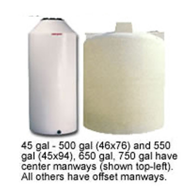
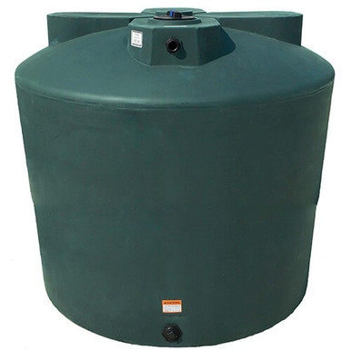
Norwesco MPN 40703 — 550 Gallon Vertical Water Tank (listed at $789.99)
- Diameter ~64 inches (5.33 ft), height ~52 inches (4.33 ft)
- Projected area Af = 5.33 * 4.33 = 23.1 sqft
- Empty weight ~165 lb
At 130 mph coastal: qz = 0.00256 * 0.85 * 1.0 * 0.95 * 1.0 * 130^2 = 35.0 psf. F = 35.0 * 0.85 * 0.7 * 23.1 = 481 lb lateral. Overturning moment ~1,041 ft-lb. Resisting moment from empty weight at center of base ~440 ft-lb. Net uplift on tie-downs required.
At 110 mph inland: qz = 25.1 psf. F = 345 lb. Overturning moment 747 ft-lb vs resisting 440 ft-lb. Engineered tie-downs still required.
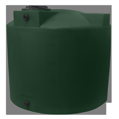
Norwesco MPN 40704 — 1100 Gallon Vertical Water Tank (listed at $1,232.23)
- Diameter 87 inches (7.25 ft), height 65 inches (5.42 ft)
- Projected area Af = 7.25 * 5.42 = 39.3 sqft
- Empty weight ~285 lb
At 130 mph coastal: F = 35.0 * 0.85 * 0.7 * 39.3 = 818 lb lateral. Overturning moment ~2,217 ft-lb. Resisting moment ~1,033 ft-lb. Net uplift; minimum 4 anchor points required.
At 110 mph inland: F = 587 lb. Overturning ~1,591 ft-lb vs resisting 1,033 ft-lb. 2-4 anchor points minimum.
Snyder MPN WB46 — 1500 Gallon Vertical Water Storage (listed at $1,540.00)
- Diameter 86 inches (7.17 ft), height 70 inches (5.83 ft)
- Projected area Af = 7.17 * 5.83 = 41.8 sqft
- Empty weight ~350 lb
At 145 mph coastal Houston: qz = 43.7 psf. F = 43.7 * 0.85 * 0.7 * 41.8 = 1,087 lb lateral. Overturning ~3,168 ft-lb. Resisting ~1,255 ft-lb. 4-6 anchor points; engineered tie-down kit.
At 110 mph inland Plains: F = 614 lb. Overturning ~1,790 ft-lb vs resisting 1,255 ft-lb. 2-4 anchor points sufficient with engineered base ring.
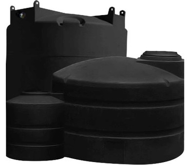
Norwesco MPN 42040 — 2500 Gallon Vertical Water Tank (listed at $1,990.00)
- Diameter 102 inches (8.5 ft), height 79 inches (6.58 ft)
- Projected area Af = 8.5 * 6.58 = 55.9 sqft
- Empty weight ~400 lb
At 130 mph coastal: F = 35.0 * 0.85 * 0.7 * 55.9 = 1,164 lb lateral. Overturning ~3,827 ft-lb. Resisting ~1,700 ft-lb. Engineered tie-down required, 4-6 anchor points minimum.
At 110 mph inland: F = 835 lb. Overturning ~2,747 ft-lb vs resisting 1,700 ft-lb. 4 anchor points typical.
Norwesco MPN 42044 — 5000 Gallon Vertical Water Tank (listed at $4,199.99)
- Diameter 119 inches (9.92 ft), height 112 inches (9.33 ft)
- Projected area Af = 9.92 * 9.33 = 92.6 sqft
- Empty weight ~750 lb
At 150 mph coastal Gulf: qz = 46.7 psf. F = 46.7 * 0.85 * 0.7 * 92.6 = 2,572 lb lateral. Overturning ~12,000 ft-lb. Resisting ~3,719 ft-lb. Engineered tie-down with 6+ anchor points + concrete pad with embedded anchor-bolt ring.
At 110 mph inland: F = 1,388 lb. Overturning ~6,476 ft-lb vs resisting 3,719 ft-lb. 4-6 anchor points to engineered concrete pad.
Coastal vs Inland: Engineering Implications
| Factor | Coastal (Exposure D, V 140-180) | Inland (Exposure C, V 105-120) |
|---|---|---|
| Foundation | Concrete pad with embedded anchor ring; stamped engineering for >1500 gal | Compacted gravel or concrete pad; stamped engineering for >3000 gal |
| Anchor type | Stainless 304 / 316 wedge or epoxy anchor; 5/8-inch min diameter | Galvanized 1/2-inch wedge; 5/8-inch on >3000 gal |
| Strap material | Stainless cable or polyester webbing rated 5,000 lb working load | Galvanized cable or webbing 2,500-5,000 lb working load |
| Anchor count (1100-2500 gal) | 4-6 minimum, 60-degree spacing | 2-4 minimum, opposing pairs |
| Anchor count (5000+ gal) | 6-8 with engineered base ring | 4-6 with engineered base ring |
| Inspection cycle | Annual + post-storm | Biennial + post-severe-weather |
Anchor Bolt Sizing
For a 5/8-inch wedge anchor in 4,000 psi concrete with 4-inch embedment, allowable tension load (per ACI 318-19 Chapter 17 anchorage provisions and manufacturer-published values) is approximately 2,500-3,500 lb. Allowable shear is 3,000-4,000 lb. For a 1/2-inch wedge anchor at the same embedment, allowable tension is roughly 1,500-2,000 lb.
For the 2500-gallon tank example above (overturning moment 3,827 ft-lb at 130 mph coastal), distributing that moment across 6 anchors on a 6-foot base diameter circle gives approximately 425 lb tension per anchor at peak — well within 5/8-inch wedge anchor capacity even with safety factor. The engineering driver is not anchor capacity at the load case; it is anchor placement, embedment depth, and concrete edge distance to prevent breakout failure.
Concrete Pad Engineering
A polyethylene tank exerts essentially uniform vertical load on its base when full. The pad design accommodates dead load (full tank weight) plus the wind-induced uplift envelope. Typical pad specifications:
- Pad thickness: 6-inch minimum for tanks up to 3000 gallon; 8-inch for 5000+ gallon. ACI 318 minimum reinforcement applies.
- Pad diameter or width: tank diameter plus 12 inches minimum, allowing anchor edge distance per anchor manufacturer specification (typically 4-6 inches from anchor to concrete edge for full capacity).
- Reinforcement: #4 rebar at 12-inch on-center each direction, top and bottom, with 3-inch cover.
- Anchor embedment: 4-inch minimum for 1/2-inch wedge anchors, 4.5-5 inches for 5/8-inch.
- Pad surface: broom-finished, level within 1/4-inch over the tank footprint per Norwesco / Snyder installation requirements.
Tie-Down Strap Configuration
Strap-style tie-downs (vs anchor-bolt-only at the base) handle the overturning moment more efficiently because they engage the upper portion of the tank where the load is applied. Typical configurations:
- X-pattern over-the-top: two crossing straps anchored at four points around the base. Most common kit shipped with Norwesco / Snyder tanks.
- Star pattern: 4 or 6 straps from a top central ring radiating to base anchors. Used for tanks taller than 8 feet where moment arm is significant.
- Cinch belt at base + over-top: cinch belt around the base shoulder with vertical straps over the dome. Used for high-aspect-ratio tanks (h/D > 2).
Strap material selection follows the coastal vs inland split above. Stainless cable with 5/8-inch turnbuckles is the workhorse for hurricane zones; galvanized cable with 1/2-inch turnbuckles is sufficient inland. UV-rated polyester webbing is acceptable for tanks installed under cover but degrades unpredictably under outdoor sun exposure.
Code and Standard References
- ASCE 7-22 — Minimum Design Loads and Associated Criteria for Buildings and Other Structures. The base reference for wind-load calculation. Section 29.4 covers wind loads on Other Structures including tanks.
- ASCE 7-22 Figure 26.5-1B — Basic Wind Speeds for Risk Category II structures.
- ASCE 7-22 Table 29.4-1 — Force Coefficients for Other Structures (Cf for tanks).
- ACI 318-19 Chapter 17 — Anchoring to Concrete. Anchor design provisions for tension, shear, and combined loading.
- 2024 IBC Section 1609 — Wind Loads. Requires ASCE 7 compliance for wind design and references the wind-speed maps.
- 2024 IBC Section 1605 — Load Combinations. Load combinations including wind for ultimate-strength design.
- FBC 2023 (Florida Building Code) Section 1620 — High-Velocity Hurricane Zone provisions for Miami-Dade and Broward counties.
- ASTM A325 — Standard Specification for Structural Bolts (when used in tie-down hardware).
- ASTM A153 — Standard Specification for Zinc Coating on Iron and Steel Hardware (galvanized hardware specification).
- ASTM A276 — Standard Specification for Stainless Steel Bars and Shapes (304 / 316 anchor materials).
Common Mistakes
Mistake 1: Sizing tie-downs for full-tank weight
The tie-down system must hold the empty tank in design wind. Operators sometimes skip tie-downs entirely on the assumption "the tank will always have water in it." Operations reality: tanks are emptied for cleaning, inspection, repair, and seasonal storage. Tie-down design must assume worst case.
Mistake 2: Anchoring to asphalt or compacted gravel
Wedge anchors in asphalt or bare gravel will pull out at modest tension load. Concrete pad with engineered embedment is the only reliable anchor base for tanks above 1000 gallon in any wind zone above 100 mph design.
Mistake 3: Over-tightening straps
Straps should be snug, not tensioned to creep the tank shell. Polyethylene relaxes under sustained load; over-tightened straps cause permanent shell deformation that can compromise the tank within 1-3 years. Manufacturer kit instructions specify finger-tight plus a quarter-turn on turnbuckle as the typical target.
Mistake 4: Galvanized hardware in coastal salt environment
Galvanized cable and turnbuckles begin red-rusting within 6-12 months of coastal salt exposure. Stainless 304 minimum (316 preferred for direct salt-spray) is the engineered specification within 5 miles of saltwater.
Mistake 5: Ignoring topography amplification
ASCE 7 Kzt for hilltop or escarpment locations can be 1.3-1.5, which raises effective wind pressure by 70-125%. A tank installed on an exposed ridge in a "moderate" wind zone may face design loads equivalent to a coastal install. Verify Kzt for the project site, not the regional zone.
How OneSource Specifies
Our default tie-down guidance:
- Identify project ZIP and pull basic wind speed V from ASCE 7-22 Hazard Tool.
- Determine Exposure Category (C inland, D within 600 ft of saltwater shoreline).
- Compute design pressure and lateral force using the methodology above, or work from the worked-example tables.
- Select tie-down kit appropriate for the wind force; engage a stamping engineer for tanks above 3000 gallon in coastal zones or above 5000 gallon inland.
- Specify concrete pad with embedded anchor ring per ACI 318-19 Chapter 17.
- Schedule annual inspection (post-storm where applicable).
SKUs referenced: Norwesco MPN 40703 (550 gal vertical water, listed at $789.99), MPN 40704 (1100 gal, listed at $1,232.23), MPN 42040 (2500 gal, listed at $1,990.00), MPN 42044 (5000 gal, listed at $4,199.99); Snyder Industries MPN WB46 (1500 gal vertical, listed at $1,540.00). All BC list prices exclude LTL freight; quote freight separately per ZIP via the Freight Estimator or by phone at 866-418-1777.
Internal Resources
- Hurricane Season Tie-Down, Strap, and Anchor Engineering
- Foundation Pad Engineering for Vertical Polyethylene Tanks
- Site Survey Checklist for Tank Installation
- Installation Walkthrough for Vertical Polyethylene Tanks
- Aboveground vs Belowground Tank Engineering
- Florida Tank Storage Regulations
- Texas Tank Storage Regulations
- Freight Cost Estimator
Source Citations
- ASCE 7-22 — Minimum Design Loads and Associated Criteria for Buildings and Other Structures
- ASCE 7-22 Section 29 — Wind Loads on Other Structures (Chimneys, Tanks, Rooftop Equipment)
- ASCE 7-22 Figure 26.5-1B — Basic Wind Speeds, Risk Category II
- ASCE 7-22 Table 29.4-1 — Force Coefficients for Other Structures
- ACI 318-19 Chapter 17 — Anchoring to Concrete
- 2024 International Building Code Section 1609 — Wind Loads
- 2024 International Building Code Section 1605 — Load Combinations
- 2023 Florida Building Code — High-Velocity Hurricane Zone Provisions
- ASTM A325, A153, A276 — Bolt and anchor material specifications
- ASCE 7 Hazard Tool (asce7hazardtool.online) — Project-specific wind-speed lookup
- OneSource Plastics master catalog data, 2026-03-26 snapshot (9,419 products)
Recommended Tanks for This Guide
Live pricing, updated automatically · estimate freight to your ZIP.