Cold-Weather XLPE Tank Failure-Mode Sequencing: From Ice Nucleation Through Wall-Thickness Gradient, Micro-Cracking, Hydrostatic Shock, and Permeation Runaway - The Five-Stage Sequence That Splits Tanks at Minus 25 Celsius


Cold-weather failure of crosslinked polyethylene (XLPE) tanks is rarely a single-event catastrophe. It is the end-state of a five-stage sequence that begins with ice nucleation on the tank wall, progresses through a wall-thickness gradient that produces internal stress, develops into micro-cracking on the inner surface, suffers a hydrostatic shock event from a fill or thaw cycle, and concludes with permeation runaway in which the now-cracked wall lets stored chemistry permeate the tank wall faster than the polymer can withstand. Each stage is preventable individually. Each stage compounds the next. The full sequence has been documented in field-failure investigations across the upper Midwest, the Canadian prairie provinces, and the Alaskan interior, and it produces a characteristic split-pattern that experienced tank operators recognize on sight.
This guide walks each of the five stages, the mechanical and chemical engineering at each transition, the field indicators that flag impending progression to the next stage, the corrective interventions available at each stage, and the cold-weather tank specification that interrupts the sequence at the start. Reference standards include ASTM D1998 for polyethylene tank manufacture, ASTM D746 for low-temperature brittleness of plastics, ASTM D5045 for plane-strain fracture toughness, and the cold-weather resin specifications published by Exxon Mobil and SABIC for rotomolding-grade polyethylene.
1. Stage One: Ice Nucleation on the Tank Wall
The starting condition is a partially-filled XLPE tank in service with stored water, dilute chemistry, or aqueous solution. The tank is in winter operation at outdoor ambient. As ambient temperature drops below the storage solution freezing point (0 deg C for water, -2 to -25 deg C for various solutions depending on solute), the wetted tank wall surface begins to nucleate ice crystals.
The nucleation site engineering matters. Smooth, clean polyethylene wall surfaces nucleate ice slowly because the polymer surface is hydrophobic and ice-crystal nucleation requires either heterogeneous sites (scratches, inclusions, fitting joints) or substantial supercooling (3-5 deg C below freezing point). A new XLPE tank with smooth wall surfaces will hold supercooled liquid for hours before ice forms, then form ice rapidly at the few nucleation sites available.
The field indicator at this stage: ice mass concentrated at fittings, manway penetrations, and tie-down strap contact points where the wall is mechanically disturbed. Operators sometimes mistake this for "the fittings froze first" - in fact the fittings nucleated first because of the geometric discontinuity, and bulk ice formation followed.
Stage-one intervention: insulation jacket on the tank exterior. R-7 minimum (1.5 inch closed-cell polyurethane spray foam or equivalent) prevents the wall surface from reaching nucleation temperature in any but the most severe cold events.
2. Stage Two: Wall-Thickness Gradient and Internal Stress
Once ice has nucleated and grown to a 5-10 mm layer on the inner wall surface, the system has developed a wall-thickness gradient. The XLPE polymer wall has its design thickness (typically 0.4 to 0.6 inch / 10-15 mm). The ice layer has its grown thickness. The combined wall now has a thermal gradient: outer surface at ambient (-25 deg C), polymer-ice interface at ice formation temperature (-1 to -3 deg C depending on solute), and ice-liquid interface at the bulk freezing point (0 deg C for water).
The thermal gradient creates a mechanical stress gradient. Polymer at the outer surface contracts as it cools toward ambient. Polymer at the inner surface is held closer to 0 deg C by the ice. The polymer wall is therefore in compression at the inner surface and tension at the outer surface. The magnitude of this stress depends on the polymer thermal expansion coefficient (HDPE around 130 microstrain per deg C, XLPE around 120 microstrain per deg C in the radial direction), the temperature differential across the wall (10 to 30 deg C in severe cold), and the polymer modulus at low temperature (modulus rises from 1 GPa at 25 deg C to 2-3 GPa at -25 deg C).
The arithmetic: 25 deg C wall-thickness gradient on XLPE produces approximately 3,000 microstrain (0.3% strain) at the outer wall surface. Multiplied by the 2.5 GPa modulus at -25 deg C, the outer-surface tensile stress is approximately 7.5 MPa - well below the polymer yield strength but significant in the context of what comes next.
Field indicator at this stage: barely visible. The tank looks fine externally. A skilled operator with a stress-relaxation indicator (or simply with experience reading tank wall flexure during cold-weather pressure cycling) can detect the wall stiffness change. Most operators will not notice this stage at all.
Stage-two intervention: prevent ice formation through Stage One mitigation, OR maintain liquid temperature above 5 deg C through heat tracing. Heat trace at 8-12 W/m on the lower tank wall combined with R-5 minimum insulation prevents the gradient from developing.
3. Stage Three: Micro-Cracking on the Inner Surface
The wall-thickness gradient described in Stage Two is normally tolerated by XLPE because the polymer has substantial fracture toughness reserve. The fracture-toughness reserve is consumed when (a) the polymer ages and HALS UV stabilizer is depleted at the outer surface, (b) the ice cycle repeats with thermal stress excursion above the steady-state gradient, or (c) a localized stress concentration appears at a wall imperfection.
Micro-cracking initiates at the inner wall surface where ice contact creates a complex stress state - the polymer is in compression from thermal gradient but is being expanded by ice volume (water-to-ice expansion is approximately 9% by volume). The combined stress state creates surface micro-cracks of 50-200 micrometer depth. The cracks are too small to see by eye and too small to leak; they are damage accumulation that compromises the polymer's ability to resist later loading.
The crack initiation rate depends on the number of freeze-thaw cycles per winter, the temperature minimum reached, the rate of temperature change (slow cooling more forgiving than rapid cooling), and the polymer aging. ASTM D746 brittleness testing on XLPE coupons shows that virgin material survives 100+ freeze-thaw cycles at -40 deg C before micro-cracking develops; UV-aged material at 10 years outdoor exposure survives 20-30 cycles before cracking.
Field indicator at this stage: typically none externally. An operator who removes the tank from service for inspection and uses dye-penetrant testing on the inner wall surface can detect the cracking pattern. Most tanks are not inspected at this stage.
Stage-three intervention: replace the tank, OR commit to interrupting Stages One and Two going forward AND accepting reduced service-life expectation.
4. Stage Four: Hydrostatic Shock
The micro-cracked wall now waits for a triggering event. The most common trigger is a hydrostatic shock during fill or thaw:
- Fill event: tank is partially full, ice is present on the wall, operator initiates fill. Incoming liquid (typically warmer than ice) creates rapid temperature rise at the ice-water interface. Ice melts asymmetrically. The thermal stress field reverses faster than the polymer can relax. Combined with hydrostatic pressure rise as the tank fills, the stress at the existing micro-cracks reaches critical intensity.
- Thaw event: ambient temperature rises from extreme cold. Ice on the inner wall melts faster at the warmer outer perimeter than at the colder dome center. Tank wall returns to design temperature non-uniformly. Thermal stress reversal couples with hydrostatic pressure of the no-longer-supported water column.
- Mechanical impact: snow plow strike, vehicle impact, falling ice from adjacent structure. Impact-loading on a micro-cracked tank wall produces brittle fracture rather than the ductile deformation that virgin XLPE would tolerate.
The shock event extends the existing micro-cracks into through-wall cracks. The signature failure pattern is a vertical split, 4-12 inches in length, originating at the inner wall surface and propagating outward. The split typically appears at 1/3 to 1/2 of the tank height where the combined hydrostatic + thermal stress is maximal.
Field indicator at this stage: tank leaks. The leak is typically slow at first - water seepage through the partially-extended crack - and accelerates over hours as the crack opens further under continued hydrostatic load.
Stage-four intervention: emergency drain to relieve hydrostatic load, isolate the tank from service, evaluate for repair vs replacement. Welded XLPE patch repair is sometimes feasible for cracks under 6 inches if the crack edges are clean and the wall temperature can be brought to welding range. Most tanks that reach Stage Four are replaced rather than repaired.
5. Stage Five: Permeation Runaway
The final stage is the post-failure mode where a partially-cracked tank is returned to service with the assumption that the visible leak has been patched but the underlying micro-crack network remains. The chemistry stored in the tank now permeates the cracked wall faster than it does virgin polymer.
For water service, permeation is typically inconsequential - water permeation through 100-micrometer cracks is slow enough that the operator does not notice. For chemistry service, the permeation rate matters. Sodium hypochlorite vapor permeating outward through cracks creates an exterior odor signature. Caustic permeating outward attacks the tank exterior coating and any adjacent metal hardware. Solvent permeating outward creates an exterior vapor exposure that may exceed OSHA permissible exposure limits at the tank surface.
Permeation runaway is the failure mode that justifies tank replacement rather than crack patching even when the patched crack appears stable. A patched Stage Four crack at 0 deg C may reopen at -25 deg C the next winter; the underlying micro-crack network is not addressed by the patch.
Field indicator at this stage: persistent odor signature exterior to the tank, exterior coating damage, and seasonal pattern of leak recurrence at the same wall location.
Stage-five intervention: replace the tank. Continued service of a Stage Five tank is operationally inappropriate.
6. Specification That Interrupts the Sequence at Stage Zero
The cold-weather tank specification that prevents the sequence from starting:
- XLPE construction - higher fracture toughness at low temperature than HDPE. ASTM D746 brittleness temperature -75 deg C for typical XLPE vs -40 deg C for HDPE.
- Cold-weather resin grade - specify resin with ASTM D746 brittleness temperature at least 20 deg C below your design minimum ambient. For -25 deg C ambient, specify resin tested to -45 deg C minimum.
- Insulation jacket - R-7 closed-cell polyurethane or fiberglass alternative. Prevents wall surface from reaching ice-nucleation temperature.
- Heat tracing - 8-12 W/m on lower tank wall. Maintains liquid temperature above 5 deg C in extreme cold.
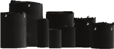
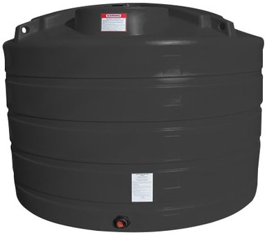
- Tank color white or natural - solar gain on warmer days helps offset overnight cooling. Black tank in northern climate is a worse choice than white because the tank wall tracks ambient more closely.
- Vent freeze protection - heat-traced vent riser with insulation. Vent ice blockage is a Stage Four trigger because it creates pressure-vacuum cycling.
- Tie-down compensation - thermal contraction of the tank in cold weather pulls the tank toward its center. Tie-down hardware must allow this dimensional change. Rigid tie-down on a contracting tank is itself a Stage Four trigger.
- Annual cold-weather inspection - visual inspection of tank wall and fittings prior to each winter season. Document baseline condition for comparison year-over-year.
For cold-climate XLPE tank selection in our catalog range, the appropriate selections include the Snyder SII-5990102N42 1,000 gallon XLPE Captor double-wall and the Snyder SII-5490000N42 1,550 gallon XLPE Captor double-wall. The double-wall annular space provides additional thermal buffering that delays ice nucleation on the inner wall, and the secondary containment provides leak isolation if Stage Four occurs despite preventive measures.
7. Field Investigation Protocol When a Cold-Weather Failure Occurs
When a tank fails in cold weather, the post-failure investigation should establish which stage triggered the visible failure to inform future tank specification:
- Document the visible failure pattern. Photograph the crack, measure length, document orientation (vertical / horizontal / diagonal).
- Document the ambient temperature history. Pull weather data for the 30 days preceding failure. Identify the lowest ambient and the most rapid temperature change.
- Document the fill history. Was the tank filled within 48 hours of failure? At what temperature was the fill liquid?
- Document the tank age and material. New (less than 2 years) tank failure suggests Stage Two thermal-stress event without prior damage. Aged (10+ years) tank failure suggests Stages Three through Five with accumulated damage.
- If repair is contemplated, sample the wall at the crack edge for laboratory analysis. ASTM D746 brittleness testing on the sample establishes whether the wall has lost cold-weather toughness through aging.
- Document the conclusion. Determine which stage triggered the failure and whether replacement should specify upgraded material or upgraded thermal protection.
8. Procurement and Operational Action Checklist
- Identify your design minimum ambient temperature. Use the local climate data minimum-of-30-year value, not the typical winter minimum.
- Specify XLPE construction for any tank in service below 0 deg C ambient. HDPE is acceptable above 0 deg C only.
- Specify cold-weather resin grade with documented ASTM D746 brittleness at least 20 deg C below design minimum.
- Specify R-7 minimum insulation jacket and heat tracing for any tank in service below -10 deg C ambient.
- Specify white or natural tank color for cold-climate service.
- Specify vent heat tracing and insulation. Plan for vent freeze protection from initial procurement, not as a retrofit.
- Specify tie-down hardware that accommodates thermal contraction. Avoid rigid bolt-down; specify strap with elastic compensation or with sliding slot detail.
- Develop the annual cold-weather inspection SOP. Schedule inspection in October or November before first hard freeze.
- Document the cold-weather tank service-life expectation in the procurement file. Realistic expectation in -25 deg C service is 12-15 years for XLPE with full thermal protection; less if any thermal protection is omitted.
- Budget for tank replacement at the projected service-life endpoint. Cold-weather tanks are not 30-year assets; treat them as 15-year capital with planned replacement.
OneSource Plastics carries the XLPE polyethylene tanks suitable for cold-weather service across the Norwesco, Snyder, and Enduraplas product lines. For cold-weather tank specification with insulation and heat-tracing engineering, call us at 866-418-1777 with your design minimum ambient, planned chemistry, and operational temperature targets. Reference pricing for representative SKUs: Snyder SII-5990102N42 1,000 gallon XLPE Captor at $3,200 list; Snyder SII-5490000N42 1,550 gallon XLPE Captor at $4,500 list; Norwesco N-40146 1,500 gallon vertical at $1,895 list. LTL freight to your ZIP is quoted via the freight estimator.
For complementary reading on cold-weather tank engineering, see our HDPE vs XLPE freeze-thaw cycle guide, the low-temperature mechanical behavior guide, and the cold-climate insulation and heat-tracing guide.
Recommended Tanks for This Guide
Live pricing, updated automatically · estimate freight to your ZIP.