Concrete Pad Sizing for Above-Ground Polyethylene Tanks: ACI 360R-10 Framework and the ACI 318 Boundary


A full above-ground poly tank is a heavy, flexible, evenly distributed load sitting on its own flat bottom. Get the pad right and the tank lasts its full service life; get it wrong — a high spot, a soft corner, an undersized slab — and you concentrate stress into the wall and invite premature cracking. Here is how to size the pad, and where the engineering crosses from a simple slab-on-ground into structural-design territory.
Start with the load
A filled vertical tank carries its entire weight straight down onto its base. Estimate it directly:
- Filled weight = capacity (gal) × fluid density (lb/gal) + empty tank weight. Water is about 8.34 lb/gal; a 1.5 specific-gravity chemical is about 12.5 lb/gal.
- A 2,500-gallon water tank holds roughly 20,850 lb of water plus the tank — over ten tons on the pad.
- A 5,000-gallon tank doubles that to roughly 41,700 lb of water.
- Bearing pressure = filled weight ÷ footprint area. Spread over the tank base, that lands within the range of a properly built slab on competent subgrade — but only if the support is continuous.
Size and shape the pad
- Extend beyond the tank. The slab should exceed the tank diameter by roughly 6–12 inches all around so no part of the base overhangs an edge.
- Level and smooth. Follow the manufacturer tolerance (commonly within about 1/8 inch per foot). Continuous full-footprint support is the goal — never a ring or piers under a flat-bottom poly tank.
- No point loads. A single rock, bolt, or high spot under the base concentrates stress — a classic crack origin.
- Compacted granular base. Place the slab on a well-compacted, free-draining subbase; poor subgrade is the most common cause of slab failure.
The ACI boundary: 360R-10 vs 318
Two American Concrete Institute documents frame the design. ACI 360R, Guide to Design of Slabs-on-Ground, covers exactly this case — a slab bearing on soil, designed around subgrade support and the concrete’s modulus of rupture rather than as an elevated structural member. For small and mid-size tanks on good subgrade, a reinforced slab-on-ground designed to 360R principles is the right tool.
The boundary to ACI 318, Building Code Requirements for Structural Concrete, is crossed when the concrete stops acting as a slab-on-ground and starts acting as a structural element — an elevated slab, a pile-supported cap, a footing carrying the load past weak soil, or any case where the local code requires structural design provisions. Large tanks, poor or expansive soils, and elevated supports all push you across that line.
Climate and drainage
- Frost. In freezing climates, protect against frost heave — carry footings below the local frost line and keep water from collecting and freezing under the slab.
- Drainage. Grade the surrounding ground so water runs away from the pad; a saturated, eroding subgrade undermines even a good slab.
- Anchoring. An empty poly tank is light and can move in wind before it is filled — plan anchor points into the pad where wind or seismic loads apply.
Bottom line
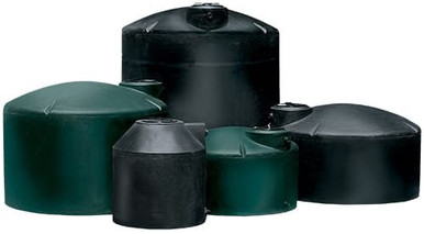
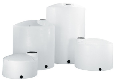
Size the pad to the filled load, support the whole footprint continuously and dead level, and keep the design on the slab-on-ground side of the 360R/318 line unless a tank size or soil condition pushes you into structural territory — then bring in a PE. The tanks above show typical 2,500 and 5,000-gallon footprints to plan around.
Recommended Tanks for This Guide
Live pricing, updated automatically · estimate freight to your ZIP.