Tank Multi-Tank Manifold Design: 2-Tank vs 4-Tank vs 8-Tank Header + Common-Drain Engineering


A single-tank install is a known-quantity engineering exercise. A multi-tank manifold — two, four, eight, or more tanks tied to a common fill, suction, or drain header — is where pressure equalization, hammer-pulse propagation, vacuum-cascade collapse, and uneven-draw silting begin to matter. This pillar walks the engineering on multi-tank header design at the three scales operators actually deploy: 2-tank parallel, 4-tank quad-rack, and 8-tank bulk-storage farm. Real Norwesco, Snyder, and Bushman SKUs throughout. Reference codes are ASME B31.3 (Process Piping), ASTM D1998 (Polyethylene Upright Tanks), ANSI/HI 9.6.6 (Pump Suction Piping), NFPA 30 (Flammable and Combustible Liquids), and 40 CFR 112 (SPCC).
The fundamental insight that drives multi-tank engineering: when you parallel two or more tanks on a common header, the tanks are no longer independent. They share pressure transients, fill imbalances, vapor space, and suction-side vortexing. Get the header design right and you get N-tank capacity at single-tank reliability. Get it wrong and you get N-tank capacity at 1/N-tank reliability — and a much higher consequence when one tank fails (because it can siphon-drain or pressurize the others).
The Three Common Configurations
| Configuration | Typical Volume | Use Case | Header Complexity |
|---|---|---|---|
| 2-tank parallel | 2,000-10,000 gal total | Backup / redundancy / buffer | Low |
| 4-tank quad-rack | 8,000-40,000 gal total | Process feed with rotation / cleaning | Medium |
| 8-tank bulk farm | 40,000-150,000 gal total | Bulk storage, batch staging | Engineered |
Configuration #1: 2-Tank Parallel — The Buffer Pair
The 2-tank parallel install is the simplest multi-tank case. Two tanks of identical capacity — typically Norwesco 1500-gallon (MPN 41036) or Snyder 2500-gallon (MPN 44801-class) — are connected at the bottom by a common suction header and at the top by an equalization line.
2-tank header design rules
- Common suction header: bottom-outlet bulkhead on each tank, tied via 2- or 3-inch CPVC or Schedule-80 PVC into a common pickup. Header diameter at minimum equal to the larger of the two tank outlets.
- Isolation valve at each tank: 2-inch full-port ball valve at each tank outlet. Allows servicing one tank without taking the other off-line.
- Top equalization line: 2-inch line tying the two tank top vents together. Provides automatic level equalization so one tank doesn't drain ahead of the other (when both are on a common suction).
- Vapor equalization: if the chemistry vents (bleach, anhydrous solvent), tie the vent lines to a common scrubber via 3-inch line. Ensures both tanks see the same vent system rather than one venting twice as much.
- Single overflow point: tie both tank overflows into a common 4-inch line (one size up from the larger overflow) routed to secondary containment.
2-tank pump suction
The pump on a parallel pair needs careful suction-side design per ANSI/HI 9.6.6. With both tanks open, the suction will pull from whichever tank has lower head loss — usually the closer tank. This causes uneven drain, where one tank empties first and creates air entrainment at the pump inlet. Solutions:
- Rotation valving: manually alternate primary tank weekly via the isolation valves. Operator awareness required.
- Automated alternation: motorized ball valves on each isolation tied to a duty cycle controller.
- Top-equalization line: the 2-inch line at the top equalizes liquid levels between the tanks via static head, evening out the suction draw.
For 2-tank residential or small commercial water-storage applications, the equalization line is sufficient and the manual rotation is rarely needed. For chemistry feed tanks where both are filled separately to verify QA per batch, automated alternation is standard.
Configuration #2: 4-Tank Quad-Rack — Process Rotation
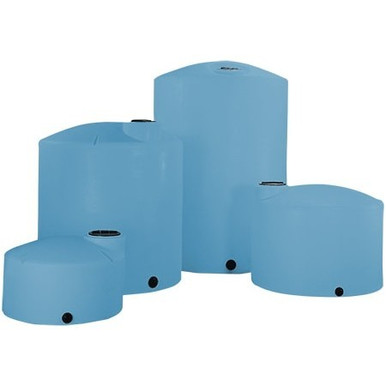
The 4-tank rack supports operations where one tank is in service, one is filling, one is on standby, and one is in cleaning or inspection at any given time. Typical capacities: 4 x Norwesco 2500-gallon (MPN 41680) or 4 x Snyder 5000-gallon for 10,000-20,000 gallon working volume.
4-tank header design
The quad-rack uses two parallel headers — one for fill, one for suction — with each tank gated by isolation valves on both sides:
- Common fill header (top): 3- or 4-inch CPVC or Schedule-80 PVC tied to a fill manifold. Each tank tap has a motorized ball valve and check valve. Controller selects which tank fills.
- Common suction header (bottom): 3- or 4-inch line picked up from each tank's lower outlet. Same isolation valve scheme. Controller selects which tank delivers.
- Independent vent / overflow per tank: at this scale, each tank needs its own atmospheric vent and overflow piping. Common-vented tanks at this scale see vacuum-collapse risk on rapid draw.
- Drain header (optional): 4-inch common drain at the floor, plumbed to neutralization or wastewater treatment, with a single header valve and individual tank drain valves.
- Pressure equalization: if all four tanks see the same chemistry, a 2-inch top equalization line balances levels. If they're on different batches, no equalization line — each tank is independent.
Hammer protection on multi-valve systems
Motorized valves closing against a moving fluid column create water hammer. ASME B31.3 Section 301.5.1 covers transient pressure analysis. On a 4-tank rack with frequent valve transitions:
- Specify slow-actuating valves: minimum 5-second close on 3-inch and larger.
- Install surge tanks or pulsation dampeners on the suction header upstream of the pump.
- Install accumulator on the discharge header for any pump head over 50 psi.
- Pipe-wall thickness rated for hammer transient pressure (typically 2-3x operating pressure).
4-tank fill control logic
Two common control strategies:
- Sequential rotation: tank 1 fills to high level, controller switches to tank 2, then 3, then 4. Operator empties any one in service. Common for batch chemistry with QA between batches.
- Lead-lag with hold: two tanks are always in service (lead and lag), one is filling, one is on standby. The PLC alternates lead/lag on a duty cycle. Common for continuous service.
Configuration #3: 8-Tank Bulk Farm — Engineered Header
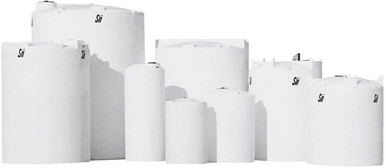
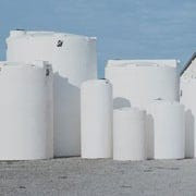
At 8 tanks and 40,000+ gallon working volume, the system is engineered, not field-assembled. Common configurations: 8 x Norwesco 5000-gallon (MPN 41524), 8 x Snyder 5000-gallon, or 4 pairs of 10,000-gallon vertical Snyder (MPN 50010-class).
Header sizing at scale
| Header | Diameter Range | Material | Pressure Rating |
|---|---|---|---|
| Fill header | 4-6 inch | SS 304/316 or Schedule-80 CPVC | 150 psi flange |
| Suction header | 6-8 inch | Schedule-80 CPVC or fiberglass | 125 psi flange |
| Drain header | 6-8 inch | Schedule-80 PVC or HDPE | Atmospheric |
| Vent / vapor manifold | 4-6 inch | Schedule-40 PVC, FRP, or SS | Low pressure |
8-tank piping geometry
The classic field error on an 8-tank farm is unequal hydraulic distance from each tank to the pump suction. Tank #1 may be 15 feet from the pump; tank #8 may be 80 feet. That's 65 feet of additional pipe friction on tank #8, which means pump suction draws preferentially from tank #1 even with both isolation valves open.
Solutions:
- Z-pattern header: headers route in a Z so total path length to each tank is matched within 10%. ANSI/HI 9.6.6 recommends this.
- Reverse-return loop: suction header taps each tank in sequence and returns past all tanks before reaching the pump. Total path length is identical for each tank.
- Forward-supply, reverse-return: classic balanced loop pattern from HVAC engineering, applied to chemistry farms.
8-tank vapor management
Vapor connection between 8 tanks is critical — and dangerous. On bleach service, off-gassing chlorine can cascade through a common vapor manifold. On petroleum service, vapor transfer creates LEL hazards in tanks that might be otherwise empty. NFPA 30 Section 21.4 and 27.4 cover the requirements:
- Each tank must have its own pressure-vacuum vent valve sized for its individual fill / draw rate.
- If a common vent header is used, each tank tap requires a flame arrestor (NFPA 30 Section 21.4.3).
- Vacuum breaker on each tank: critical to prevent vacuum cascade where pumping out of one tank pulls vacuum on the others through the vent header.
- Pressure transmitter on the common header tied to PLC: if header pressure deviates more than 0.25 psi from atmosphere, the PLC trips fill and pump operations.
8-tank common drain
The drain header on a bulk farm is the most under-engineered part of the system on most installs. Cleaning one tank requires draining 5,000+ gallons; if the drain header isn't sized for that flow, the drain becomes a bottleneck and the tank stays out of service for days.
- Common drain sized for full tank drainage in under 4 hours: typically 6-inch minimum on 5,000-gallon tanks, 8-inch on 10,000+.
- Each tank drain has its own isolation valve plus a drain-header isolation valve.
- Drain header slopes to a common collection sump or neutralization tank — never to grade.
- Drain header includes flushing capability: connect a freshwater line at the header inlet so drain piping can be flushed clean between chemistry batches.
Vacuum Cascade — The Multi-Tank Failure Mode
The vacuum-cascade failure is the silent killer of multi-tank systems. Sequence:
- Tank #1 is being pumped out fast.
- Common vent header is undersized; pump-out rate exceeds vent inflow capacity.
- Vacuum builds in tank #1.
- Vacuum propagates through the common vent header to tanks #2-#8.
- Empty or low-fill tanks have less hydrostatic head to resist vacuum collapse.
- One or more "victim" tanks implode at -0.5 to -1 psi differential.
Polyethylene tanks designed per ASTM D1998 are atmospheric — they have no pressure or vacuum rating. Even small negative differentials cause permanent deformation. The fix: vacuum breakers on every tank, sized for the maximum draw rate from the largest tank in the system.
Suction Vortex on Common Header
When pump suction is on a common header pulling from multiple tanks, the lowest-resistance tank empties first. As that tank approaches empty, vortex forms at the outlet, pulling air down into the suction line. Air entrainment cavitates the pump.
ANSI/HI 9.6.6 sets minimum submergence depth at the suction outlet:
- For a 2-inch outlet: minimum 12 inches submergence.
- For a 3-inch outlet: minimum 18 inches submergence.
- For a 4-inch outlet: minimum 24 inches submergence.
Implementation: low-level cutoff float switch on each tank in the rack. When the level falls below the minimum submergence depth, the tank's isolation valve closes and the controller transitions to a different tank.
Containment for Multi-Tank Farms
SPCC 40 CFR 112.7(c) requires secondary containment sized to 110% of the largest single tank, plus the displaced volume of any containment-resident equipment. Multi-tank farm containment options:
- Single dike for all tanks: sized to 110% of the largest tank. Simplest. Failure of one tank floods the entire dike, contaminating all containment.
- Individual sub-dikes: each tank in its own berm. Most expensive. Best isolation.
- Paired sub-dikes: each pair of tanks in a shared berm. Compromise. Common on 4-tank and 8-tank farms.
- Double-wall tanks (Snyder DWT series): each tank in its own integral secondary. Containment built into each tank.
SPCC review must consider: farm scale, chemistry, drain-to-disposal capacity, and emergency response time. For chemistry farms, sub-dike or double-wall is the engineering default; for water farms, single dike is acceptable.
Multi-Tank Mistakes
Mistake 1: Common vent without vacuum breakers
Vacuum cascade implodes tanks. Vacuum breaker on every tank, every time.
Mistake 2: Unequal hydraulic distance to suction pump
Far tanks never draw evenly. Use Z-pattern or reverse-return header.
Mistake 3: Undersized drain header
Cleaning one tank takes days because the drain bottlenecks. Size for 4-hour full-tank evacuation.
Mistake 4: Common vapor header without flame arrestors
NFPA 30 Section 21.4.3 violation; off-gassing in one tank can ignite vapors in another.
Mistake 5: No isolation valve at each tank
You can't service one tank without taking the whole farm offline. Always install isolation valves at each tank.
Mistake 6: Single dike on chemistry tanks
One tank failure contaminates the entire containment. Sub-dike or double-wall for chemistry.
Mistake 7: No low-level cutoff per tank
Vortex forms, air entrainment cavitates pump. Minimum submergence per ANSI/HI 9.6.6.
Mistake 8: Forgetting hammer protection on motorized valves
Motorized valve close events at 1-2 second close times spike pressure on the header. Specify 5+ second close, install dampeners.
Internal Resources
- Tank Plumbing System Design Pillar
- Tank Cleaning + Maintenance Pillar
- Aboveground vs Belowground Storage Engineering
- Insulation & Heat Tracing Engineering
- Chemical Compatibility Database
- Specialty & Metal Fabrication
- Freight Cost Estimator
Source Citations
- ASME B31.3 — Process Piping Code (Section 301.5: Transient Pressure)
- ASTM D1998 — Standard Specification for Polyethylene Upright Storage Tanks (Sections 8-9)
- ANSI/HI 9.6.6 — Rotodynamic Pump Suction Piping Practice
- NFPA 30 — Flammable and Combustible Liquids Code (Section 21.4: Vent Sizing; Section 27.4: Vapor Recovery)
- 40 CFR 112 — Spill Prevention, Control, and Countermeasure (SPCC) Plan
- API 650 / API 653 — Steel tank inspection (adapted for poly farm engineering)
- Snyder Industries Manifold Engineering Bulletin SI-MA-201
- Norwesco Multi-Tank System Bulletin (manufacturer guidance)
- OneSource Plastics master catalog data, dated 2026-03-26 snapshot (9,419 products)
Recommended Tanks for This Guide
Live pricing, updated automatically · estimate freight to your ZIP.