Groundwater Monitoring Well Placement Around Buried Polyethylene Storage Tanks: Hydrogeologic Site Characterization, Upgradient and Downgradient Well Geometry, Sampling Frequency, and Detection-Limit Discipline for Leak Detection Compliance

A buried or below-grade polyethylene storage tank in a regulated environmental setting is required by 40 CFR 264, 40 CFR 265, and parallel state environmental rules to operate inside a leak detection regime that gives early warning of containment failure. The dominant leak detection technology for buried tanks is the network of groundwater monitoring wells installed around the tank in a geometry that reflects the local hydrogeology. Where the wells are placed, how deep they are drilled, what they are sampled for, and how often the samples are analyzed are decisions with significant cost and significant compliance consequences. This article walks the hydrogeologic framework, the upgradient-downgradient well geometry, the sampling protocol, the analytical chemistry, and the integration of the well network into the site environmental compliance program.
The discussion is grounded in 40 CFR 264 Subpart F, ASTM D5092 monitoring well construction standard, EPA RCRA Groundwater Monitoring Technical Enforcement Guidance Document (TEGD), and field practice across the 5-brand polyethylene tank catalog (Norwesco, Snyder, Chem-Tainer, Enduraplas, Bushman). List pricing on each tank product page; LTL freight quoted to your ZIP via the freight estimator or by phone at 866-418-1777.
1. The Regulatory Framework Driving Groundwater Monitoring
Multiple regulatory regimes drive the groundwater monitoring requirement around storage tanks:
- RCRA Subtitle C for hazardous waste tanks. 40 CFR 264 Subpart F (for permitted facilities) and 40 CFR 265 Subpart F (for interim status facilities) establish groundwater monitoring requirements for hazardous waste management units including storage tanks. The rule requires a network of upgradient and downgradient wells, sampling at specified frequencies, statistical evaluation of results against background, and corrective action when releases are detected.
- RCRA Subtitle I for underground storage tanks. 40 CFR 280 governs underground storage tanks containing petroleum and certain hazardous substances. The rule provides multiple compliance pathways: tank-tightness testing, automatic tank gauging, vapor monitoring, groundwater monitoring, or interstitial monitoring. Sites that select groundwater monitoring as the leak detection method must comply with the well placement and sampling requirements specific to UST applications.
- State environmental programs. Many states impose additional or more stringent groundwater monitoring requirements through state environmental rules. State programs typically address petroleum tanks (state UST programs), agricultural chemistry storage (state pesticide and fertilizer rules), and industrial storage (state hazardous waste programs). The state requirements may dictate well-density, sampling-frequency, and analytical-method choices.
- Local zoning and water-quality protection. Local jurisdictions sometimes impose groundwater monitoring requirements through zoning conditions, water-supply protection ordinances, or stormwater rules. Sites in source-water protection zones for public water supplies often see the most stringent local requirements.
- Voluntary or contract-driven monitoring. Some sites install groundwater monitoring wells voluntarily to support insurance underwriting, lender requirements, or customer audit programs. The voluntary monitoring is not driven by a specific regulation but by business decisions about risk transparency and stakeholder confidence.
- The compliance documentation chain. Whatever the driver, the monitoring program produces a documentation chain: site characterization report, monitoring well construction logs, sampling and analysis plan, periodic sampling reports, statistical evaluations, and corrective-action reports if applicable. The documentation is the evidence of compliance and the working record of site environmental status.
The driver determines the rigor of the program. RCRA-driven programs are the most prescriptive; state-driven programs vary in rigor; voluntary programs allow the most flexibility but still benefit from following the prescriptive framework as a quality reference.
2. Hydrogeologic Site Characterization
The placement of monitoring wells must reflect the actual subsurface hydrogeology, which requires characterization before the wells are placed:
- The geologic setting determination. The first step is identifying the geologic setting: the unconsolidated sediments (sand, silt, clay), the bedrock (limestone, shale, granite, basalt), the depth to bedrock, the depth to water table, and the lateral continuity of formations. The setting is determined from existing geologic mapping (state geological survey publications, USGS quadrangle maps), drilling logs from nearby wells, and (when needed) site-specific soil borings.
- The aquifer identification. An aquifer is a saturated geologic formation capable of yielding water. The site may have a shallow water-table aquifer in unconsolidated sediments, a deeper confined aquifer in bedrock, or both. The aquifer of interest for tank monitoring is typically the uppermost aquifer beneath the tank: the formation that any tank release would first encounter.
- The hydraulic gradient determination. Groundwater flows from areas of high hydraulic head to areas of low hydraulic head. The hydraulic gradient (the slope of the water table or potentiometric surface) determines flow direction. Site characterization measures water levels in three or more existing or new wells to triangulate the gradient direction and magnitude. A typical site has gradient between 0.001 (one foot per thousand feet, very flat) and 0.05 (five feet per hundred feet, steep) with corresponding flow velocities of inches to feet per day.
- The hydraulic conductivity measurement. The hydraulic conductivity (the ease with which water flows through the formation) is measured by slug test, pump test, or laboratory permeability testing on core samples. Conductivity ranges from less than 0.001 feet per day (clay) to over 1000 feet per day (clean coarse sand and gravel). The conductivity together with the gradient determines actual groundwater flow velocity.
- The flow direction and velocity calculation. Flow velocity equals hydraulic conductivity times gradient divided by effective porosity. A typical sandy aquifer with conductivity of 50 feet per day, gradient of 0.005, and effective porosity of 0.25 yields velocity of one foot per day. The velocity informs the well-spacing decision and the sampling-frequency decision.
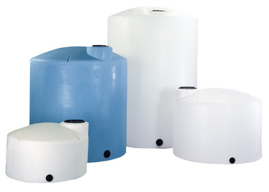
- Reference 5000 gallon tank for the characterization scope. Reference N-40164 5000 gallon Norwesco vertical as a typical industrial tank where the full hydrogeologic characterization applies. The footprint of 95 inches by 168 inches projected onto the subsurface plus a 50-foot perimeter buffer defines the area of characterization for well-placement planning.
The hydrogeologic characterization is the foundation of the monitoring program. Sites that skip the characterization end up with wells in the wrong places that miss releases or produce false alarms; sites that invest in characterization produce monitoring programs that work.
3. Upgradient and Downgradient Well Geometry
The well network around a tank or tank field follows a specific geometric framework based on hydraulic gradient direction:
- The upgradient well purpose. Upgradient wells are placed in the direction from which groundwater flows toward the tank. The wells sample groundwater that has not been affected by any tank release because the water has not yet reached the tank. Upgradient wells establish the background water quality that downgradient samples are compared against. The 40 CFR 264 rule requires at least one upgradient well; site-specific conditions may dictate two or three.
- The downgradient well purpose. Downgradient wells are placed in the direction toward which groundwater flows away from the tank. The wells sample groundwater that may carry contaminants from a tank release. The 40 CFR 264 rule requires sufficient downgradient wells to detect releases; the typical minimum is three wells positioned to span the downgradient projection of the tank footprint.
- The downgradient well spacing. The downgradient wells must be spaced closely enough that a release from any point of the tank reaches at least one well before reaching the regulated point of compliance (typically the property boundary). The spacing depends on the dispersion characteristics of the aquifer: clay aquifers with low dispersion require closer spacing than sand aquifers with high dispersion. A typical spacing for industrial sites is 50 to 100 feet between downgradient wells.
- The downgradient well distance from tank. Wells placed too close to the tank can be affected by infiltrating precipitation, leaking buried piping, and other near-surface phenomena that produce false alarms. Wells placed too far from the tank delay detection and allow plumes to spread before being identified. A typical downgradient distance is 25 to 75 feet from the tank perimeter, depending on aquifer flow velocity and tank geometry.
- The well screen depth and length. The well screen is the slotted section that admits groundwater into the well. The screen must intersect the water table at the time of low water and remain submerged at high water; a typical screen length is 10 to 15 feet, with the screen straddling the seasonal water-table fluctuation range. The bottom of the screen should be set in the formation expected to first carry any release.
- Reference 1000 gallon tank for the small-installation geometry. Reference N-40152 1000 gallon Norwesco vertical as a smaller-scale tank where a simpler well network may be acceptable. The smaller tank footprint reduces the downgradient span; some installations satisfy the regulatory requirement with one upgradient and two downgradient wells.
The well geometry is determined by the hydrogeologic characterization, the regulatory minimum well count, and the operational considerations. The placement decision is documented in the sampling and analysis plan and approved by the regulatory authority before drilling.
4. Monitoring Well Construction Standards
The construction of each well follows a defined standard to ensure the well actually samples groundwater representative of the formation:
- The drilling method selection. The drilling method depends on the formation. Hollow-stem auger is used for unconsolidated formations to about 80-foot depth. Mud rotary or air rotary is used for consolidated formations or deeper unconsolidated formations. The method is selected to avoid contamination of the borehole and to allow the planned well construction.
- The well casing material. The well casing is typically PVC schedule 40 for shallow installations in non-aggressive groundwater, or stainless steel 304/316 for deep installations or aggressive chemistry. The casing diameter is typically 2 inches for monitoring wells (sufficient for sampling and water-level measurement, smaller than production wells).
- The well screen material and slot size. The screen material matches the casing. The slot size is selected to admit groundwater while excluding the formation grains; typical slot sizes are 0.010 inch (10-slot) for fine sand, 0.020 inch (20-slot) for medium sand, 0.030 inch (30-slot) for coarse sand and gravel.
- The filter pack and seal construction. The annular space between the well screen and the borehole wall is filled with a filter pack (typically silica sand sized to be just larger than the screen slots). Above the filter pack a bentonite seal isolates the screened formation from the upper formations and from surface drainage. Above the bentonite seal a cement-bentonite grout completes the annulus to the surface.
- The surface completion. The well is completed at the surface with a protective casing (steel pipe over the PVC), a locking cap, and a concrete pad sloped away from the well. In high-traffic areas the well may be completed flush with the surface in a vault; in protected areas the well may project above grade with a stickup completion.
- The development and survey. After construction the well is developed (pumped or surged) to remove drilling fluids and develop the natural filter pack. A survey records the well location and elevation to the precision required for the gradient calculation (typically 0.01 foot of elevation precision).
- Reference 2500 gallon tank for the well construction scope. Reference N-41524 2500 gallon Norwesco vertical as the typical mid-volume tank where standard ASTM D5092 well construction applies. The well-construction cost is similar regardless of tank size; the major cost driver is the depth to water table and the geologic setting.
The well construction must be done correctly the first time. Wells with construction defects produce unreliable data, expose the site to false alarms or missed releases, and may need to be plugged and replaced at significant cost.
5. The Sampling Protocol and Analytical Chemistry
Once the wells are constructed and developed, the sampling protocol determines what data the program produces:
- The sampling frequency. 40 CFR 264 requires sampling at least semi-annually for indicator parameters and on a defined frequency (usually quarterly initially) for site-specific contaminants. Some state programs require monthly sampling; some site-specific permits require continuous monitoring. The frequency is selected to detect a release within a defined time window after release initiation.
- The sample collection method. Samples are collected by low-flow pumping, peristaltic pump, bailer, or passive diffusion sampler. The method affects sample representativeness; low-flow pumping is the modern default for most applications because it minimizes formation disturbance. The protocol includes purge-volume and stabilization-criteria requirements before sample collection.
- The indicator parameter list. 40 CFR 264 Appendix III lists indicator parameters: pH, specific conductance, total organic carbon (TOC), and total organic halogen (TOX). Changes in these parameters relative to background suggest a release without specifying the contaminant. Sites characterize the chemistry stored in the tank and add specific contaminants to the analytical list.
- The site-specific contaminant list. The contaminant list reflects the chemistry stored in the tank and the secondary contaminants that the chemistry can produce in the subsurface. For petroleum tanks the list includes BTEX (benzene, toluene, ethylbenzene, xylenes), MTBE, and total petroleum hydrocarbons. For chlorinated solvent storage the list includes the parent solvent and the daughter products (vinyl chloride, dichloroethylenes). For inorganic chemistry the list includes the cation and anion of the salt plus pH and conductivity.
- The detection limit discipline. Each contaminant has a regulatory action level (often the federal drinking water Maximum Contaminant Level or state-specific equivalent). The analytical detection limit must be lower than the action level (typically 10x lower) to provide useful early warning. The analytical method (EPA 8260 for VOCs, EPA 8270 for SVOCs, EPA 6010/6020 for metals) is selected to achieve the required detection limit.
- The chain of custody and field QA. The sample chain of custody is documented from collection through laboratory delivery. Field QA includes equipment blanks, trip blanks, and field duplicates at the prescribed frequency. The QA data validates that field handling did not introduce contamination or fail to recover analyte.
The sampling protocol determines the data quality. A weak protocol produces data that cannot defend against a release allegation; a rigorous protocol produces data that satisfies regulatory expectations and supports site management decisions.
6. Statistical Evaluation and Detection of Releases
The data from the wells must be evaluated against background to identify releases. The statistical methodology is prescriptive:
- The background data set. The first sampling rounds (typically four to eight quarters before the tank operates or before the monitoring period begins) establish the background data set. The background reflects the natural variability of groundwater chemistry at the site and serves as the baseline against which subsequent samples are compared.
- The detection-monitoring statistical methods. 40 CFR 264 Appendix IV lists allowable statistical methods including Cochran's approximation to the Behrens-Fisher t-test, prediction intervals, control charts, and tolerance intervals. The site selects a method, documents the selection, and applies it consistently. Modern programs typically use prediction intervals or control charts.
- The detected-release determination. A statistically significant exceedance of background in a downgradient well triggers the detected-release determination. The first response is verification sampling: a follow-up sample within a defined time window to confirm the original result. False alarms (statistical noise, sample contamination, transient natural variability) are screened out by verification.
- The compliance monitoring shift. Confirmed detection shifts the program from detection monitoring (looking for any change from background) to compliance monitoring (looking for exceedances of action levels for specific contaminants). The contaminant list expands, the sampling frequency may increase, and the analytical scope expands.
- The corrective action trigger. If compliance monitoring confirms that contaminants are present above action levels, corrective action is required. Corrective action ranges from continued monitoring with hydraulic containment to active remediation (pump-and-treat, in-situ chemical oxidation, monitored natural attenuation, or excavation). The action selection is based on the contaminant, the plume extent, the receptor exposure, and cost-effectiveness.
- The documentation expectation. Every step of the statistical evaluation and the corrective-action decision is documented. The documentation is the basis of regulatory communication and the defense in any subsequent litigation. Sites that document well are sites that survive regulatory scrutiny well.
The statistical evaluation closes the data-to-decision loop. The wells produce data; the statistics identify changes; the response protocol converts the change into a defined action.
7. Integration With Tank Operations and Site Compliance
The groundwater monitoring program connects to the tank operations and the broader site compliance program:
- The sampling and analysis plan (SAP) document. The SAP is the master document that specifies the well network, the sampling frequency, the analytical methods, the QA program, the statistical methods, and the response protocols. The SAP is approved by the regulatory authority before sampling begins and updated when the program changes.
- The well-status awareness in operations. The tank operator should be aware of the well locations, the sampling schedule, and the recent results. Sampling events occasionally require coordination with operations: ensuring tanks are not being filled or drawn during sampling, ensuring access to the well locations, ensuring the sampling team has the necessary safety briefings.
- The release-detection coordination. A confirmed release detected by the wells triggers an immediate response that may include: ceasing tank operations, opening the tank for inspection, performing tightness testing, transferring the contents to alternative storage, and excavating the tank for visual inspection. The tank operations team must be prepared to execute the response plan.
- The reporting timeline awareness. Detected releases trigger reporting to the regulatory authority within prescribed timelines (typically 24 hours for verbal notification, 30 days for written report). The site environmental staff manages the reporting; the tank operations team supports with the operational facts (last fill date, contents, recent activities).
- The cost integration into tank lifecycle. The monitoring program is a continuing cost across the tank service life: drilling cost (capital), sampling and analysis cost (annual operating), data management cost (annual operating), and the contingent corrective-action cost (variable). The total cost across a 20-year tank service life can approach or exceed the original tank cost. Procurement decisions about tank quality, secondary containment, and leak detection technology should consider the monitoring-program cost in the lifecycle calculation.
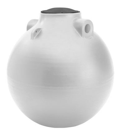
- Reference 100 gallon tank for the small-scale monitoring. Reference N-44800 100 gallon Norwesco doorway tank as the smallest-scale tank where some monitoring may apply (though most small tanks are above grade and exempt from groundwater monitoring requirements). The threshold quantity rules generally exempt tanks under 110 gallons or under specific volume thresholds for the specific chemistry and regulatory regime.
The integration is the operational reality. The monitoring program is not a separate compliance silo; it is a thread woven into the tank operations, the environmental compliance program, and the site capital planning.
8. Procurement Implications and Tank Selection
The groundwater monitoring requirement informs tank procurement decisions:
- Above-grade versus below-grade tank selection. Above-grade tank installations are typically not subject to groundwater monitoring requirements because they are not buried. Below-grade and partially-buried installations are subject to the requirements. The procurement decision between above-grade and below-grade should explicitly consider the groundwater monitoring cost as a lifecycle factor, not just the visual or footprint considerations.
- Secondary containment tank selection. Double-wall tanks with interstitial leak detection may qualify for alternative leak-detection methods that reduce or eliminate the groundwater-monitoring requirement. The double-wall premium at procurement is offset across the service life by reduced monitoring cost. The lifecycle-cost calculation can favor double-wall tanks even at higher initial cost.
- Tank material compatibility with chemistry. Polyethylene tanks have specific chemistry compatibility limits. The compatibility selection at procurement reduces the probability of release that would trigger compliance monitoring and corrective action. Investment in the correct material at procurement is much cheaper than corrective action after a release.
- Tank fittings for tightness testing. Tanks subject to tightness testing as part of the leak detection program need fittings that allow the test to be performed. The procurement specification should call out the test-port locations and sizes if the testing protocol requires them.
- The documentation deliverable. The tank documentation package (capacity certification, hydrostatic test report, material certification) feeds the site environmental records and supports the compliance position. The procurement should specify the deliverable documentation explicitly.
- The supplier-relationship value. A tank supplier that understands the regulatory framework and can support the customer's compliance work adds value beyond the tank itself. The relationship value matters across the tank service life when questions arise about material compatibility, fitting modifications, or replacement timing.
The procurement implications are most significant for sites planning new tank installations subject to groundwater monitoring. Existing installations have less flexibility but the lifecycle-cost framework still informs replacement timing decisions.
9. The Groundwater Monitoring Engineering Conclusion
Groundwater monitoring well networks around buried and below-grade polyethylene tanks are the leak-detection method specified by RCRA, state environmental rules, and many local programs. The well placement must reflect site-specific hydrogeology with characterized hydraulic gradient and conductivity. The well construction must follow ASTM D5092 standards. The sampling protocol must collect representative samples with appropriate frequency and analytical methods. The statistical evaluation must distinguish releases from background variability and trigger appropriate responses. The integration of the monitoring program with tank operations and site compliance closes the loop from data to decisions.
OneSource Plastics ships polyethylene tanks across the 5-brand catalog (Norwesco, Snyder, Chem-Tainer, Enduraplas, Bushman) in single-wall and double-wall configurations matched to the leak-detection regime. Tank specification for any specific application is performed by the customer site engineer with reference to the chemistry, the regulatory regime, and the site hydrogeology. List pricing on each product page; LTL freight to your ZIP via the freight estimator or by phone at 866-418-1777.
Recommended Tanks for This Guide
Live pricing, updated automatically · estimate freight to your ZIP.