Loadout Pad Engineering for Bulk Polyethylene Tanks: Dust Suppression, Spill Containment Geometry, Pad Slope Mathematics, Curb-and-Sump Design, and the Civil-Design Mistakes That Turn a Tank-Truck Transfer Into a Reportable Release Event


The loadout pad is the concrete (or asphalt, or gravel-and-liner) civil work where the tanker truck connects to the bulk polyethylene tank for delivery or shipment of process fluid. It is the most engineering-rich square footage on the tank-farm site, and it is the square footage where most regulatory events originate. EPA enforcement records, state-level Spill Prevention Control and Countermeasure (SPCC) inspection findings, and OSHA process-safety incident reports all show the same pattern: the spill happens during transfer, the transfer happens at the loadout pad, and the loadout pad is the part of the installation that received the least engineering attention during design.
This article walks the civil and operational engineering of loadout pads serving bulk polyethylene tanks installed by Norwesco, Snyder, Chem-Tainer, Enduraplas, and Bushman customers across agricultural, municipal, industrial, and chemical-distribution applications. The references are 40 CFR 112 (the SPCC rule), 40 CFR 264 Subpart I (RCRA container storage), API RP 540 (electrical installations in petroleum processing plants), API 2350 (overfill protection for storage tanks), the Uniform Fire Code provisions for hazardous materials handling, and field forensic data from over 200 reportable release events at chemical-distribution and agricultural-input loadout sites. The objective is the pad geometry, drainage design, dust-control treatment, and operational discipline that keeps the transfer event inside the engineered footprint and out of the storm sewer.
1. What the Loadout Pad Has to Do
The loadout pad is a single piece of civil work that has to perform six functions simultaneously: it has to support the tare weight plus loaded weight of the tanker truck without rutting or cracking, it has to drain incidental water (rainfall, washdown) to a permitted discharge point, it has to capture an unintended product release inside a containment volume sized for the worst-credible spill, it has to provide a hard surface that does not generate fugitive dust during normal use, it has to give the operator working clearance and footing during the transfer connection, and it has to do all of this in compliance with whichever combination of federal, state, and local regulations apply to the contained product.
The functions conflict. Drainage geometry that handles rainfall efficiently is the same geometry that channels a spill to the stormwater collection system. Dust suppression that keeps the surface from generating particulate is the same treatment that can become slippery during cold-weather operation. The spill containment volume that a regulator wants is volume that the operator has to walk around, which makes the transfer connection more difficult and longer-duration. The engineering that resolves these conflicts is the engineering that distinguishes a loadout pad from a parking lot.
The federal regulatory backbone is 40 CFR 112.7(c) for SPCC: secondary containment must be capable of containing oil and constructed so that a discharge will not escape the containment system before cleanup occurs. The provision applies to oil-related products at threshold storage volumes, but state programs, EPA Risk Management Plan requirements under the Clean Air Act, and DOT highway-route safety requirements expand the same logic to non-oil hazardous chemicals. The practical engineering target is independent of the specific regulation: contain the largest credible single-event release inside the engineered pad and keep storm runoff segregated from any contained product.
2. Pad Slope: The Geometry That Drains Water Without Channeling Spills
The pad slope is the first design parameter and the one that gets specified wrong most often. Two competing requirements drive the slope: rainfall has to drain off the pad to a permitted discharge point so that the pad does not become a mosquito-breeding ponded area, and any product spill has to drain to a contained sump where it can be recovered, not to the same discharge point where the rainfall goes.
The engineered solution is a two-grade pad with a perimeter curb. The pad surface slopes at 1 to 2 percent toward a centerline trough that runs the length of the pad under the tanker truck. The trough is sized for the design storm (typically a 25-year, 24-hour event for agricultural and rural-industrial sites; longer return periods for urban or environmentally sensitive sites) and discharges to a sump at the low-elevation end. The sump has a manually-operated discharge valve: in the normal state the valve is closed, the sump fills with rainfall during storms, and the operator opens the valve to discharge clean rainfall to the storm sewer after visual confirmation that no product is present. If a spill occurs the valve stays closed, the sump captures the spill, and a vacuum truck pumps the contained product to a recovery tank.
The slope mathematics: a 1 percent slope is 1 inch of fall per 100 inches (8.3 feet) of pad length. A 2 percent slope is 1 inch per 50 inches (4.2 feet). For a typical 60-foot tanker pad with a centerline trough, the slope produces 7-15 inches of elevation differential between the high edge of the pad and the centerline trough. This is enough slope to drain rainfall reliably without producing pad surfaces so steep that the operator's footing becomes hazardous or the tanker truck cannot park safely.
The slope mistake to avoid: a pad sloped from one end to the other (longitudinal slope only, no centerline trough) channels everything — rainfall and spill — to the same downslope edge. This is the geometry that produces the regulatory incident: a spill at the high end of the pad rolls down the entire length and reaches the perimeter curb at maximum velocity, splashing over the curb or finding any low spot in the curb's seal to the pavement. The two-grade with centerline trough geometry contains the spill at its origin point and gives the operator time to respond.
3. Curb Height and Containment Volume Mathematics
The perimeter curb is the secondary containment boundary. SPCC and most state programs require the containment volume to equal at least the volume of the largest single container plus a reasonable margin for precipitation. For a loadout pad serving a 6,000-gallon tanker truck, the engineering target is curb-contained volume of at least 6,000 gallons plus the 25-year, 24-hour storm event volume across the pad footprint.
The curb-height mathematics: a 60-foot by 16-foot pad has 960 square feet of containment area. A 6,000-gallon contained volume requires 6,000 / 7.48 = 802 cubic feet of capacity, which translates to 802 / 960 = 0.83 feet (10 inches) of average depth. With pad slope toward the centerline trough, the effective depth at the perimeter is greater than the average; a 12-inch perimeter curb on a 1.5 percent sloped pad provides roughly 15 inches of depth at the trough centerline and 9 inches at the high pad edge, with a calculated capacity of approximately 7,200 gallons including the trough volume itself.
The curb has to be more than a height. It has to be sealed to the pad: a curb cast monolithically with the pad, or a curb sealed with chemical-resistant joint sealant compatible with the contained product. A construction joint between the pad slab and the curb that is sealed only with conventional concrete grout is a leak path; the grout is permeable to most aqueous chemistries and degrades within a few years of exposure to product residue.
The curb breach for the tanker access ramp is the engineering detail that gets overlooked. The tanker truck has to drive onto the pad, which means there has to be a break in the curb at the access end. The break is a containment breach during a spill event unless it is engineered. The engineered detail is a removable spill berm: a heavy-duty rubber or polyurethane berm that the operator deploys across the access opening before transfer begins and removes after the tanker leaves. A concrete-curb pad without a deployable spill berm at the access is a pad with a continuous gap in its containment perimeter; the SPCC inspector who walks the site after a spill will note this in the report.
4. Surface Treatment: The Choice Between Concrete, Asphalt, and Lined Gravel
The pad surface treatment is the chemistry-specific decision. Three options dominate the field:
- Reinforced concrete with chemical-resistant sealer. The default for most chemical-distribution applications. A 6-inch reinforced concrete slab on prepared subgrade with a chemical-resistant epoxy or methyl methacrylate sealer applied to the surface. The sealer is the chemistry-specific element: epoxy systems handle acids and bases at moderate concentration; novolac epoxy and vinyl ester systems handle stronger oxidizers; specialty fluoropolymer coatings handle aggressive halogenated chemistries. Service life of the sealer is 5-15 years depending on chemistry exposure and traffic.
- Reinforced concrete with no sealer. Acceptable for water and water-based fluids where concrete is chemically stable. Cost-effective and durable; service life is essentially indefinite for the slab itself. Not acceptable for acidic, basic, or solvent-based products that attack the cement matrix.
- Asphalt with chemical-resistant overlay. Used in some agricultural and bulk-fertilizer applications where the cost of full concrete is prohibitive. Less durable than concrete; the asphalt itself is attacked by hydrocarbon solvents and many agricultural fertilizer chemistries. The chemical-resistant overlay (typically a polymer-modified asphalt or a separate chemical-resistant topcoat) is the failure point; service life is 3-7 years depending on chemistry exposure.
- Compacted aggregate with synthetic liner underneath. Used for temporary or low-volume installations where the engineered concrete pad is not justified. The liner (HDPE, EPDM, or reinforced PVC depending on chemistry) is the containment element; the aggregate is the drivable surface. Durability is limited by aggregate displacement and liner damage from sharp gravel; service life is 2-5 years for permanent installations. Not recommended for high-frequency loadout sites.
The surface-treatment selection has to match the contained chemistry across the entire envelope of products that will see the pad. A sealer specified for sodium hypochlorite is not necessarily compatible with sulfuric acid; a pad that will see both products in mixed-chemistry distribution requires a sealer with broad chemical resistance, not a chemistry-specific optimum.
5. Dust Suppression: The Particulate Problem at Dry-Bulk and Powder-Slurry Sites
Dust suppression is a specific issue at loadout pads that handle dry-bulk products (cement, fly ash, dry chemicals) or that connect to slurry tanks where the dry product is mixed before pumping. The fugitive dust from the tanker connection and the disconnection produces particulate emissions that violate Clean Air Act requirements (the National Ambient Air Quality Standards for PM2.5 and PM10), worker-exposure limits under OSHA 29 CFR 1910 Subpart Z, and community-relations expectations for industrial sites near residential areas.
The engineered approach is layered:
- Pad surface that does not generate dust under traffic. Sealed concrete generates effectively no dust; asphalt generates moderate dust as the surface oxidizes; aggregate surfaces generate substantial dust under tanker-truck traffic. The pad surface treatment has to be selected with the dust generation rate in mind, not just the chemistry compatibility.
- Tanker-connection dust collection at the transfer point. A small dust hood at the loadout connection captures the displaced air and entrained particulate during pneumatic dry-product transfer. The hood vents to a fabric-filter dust collector or to a wet scrubber depending on the product and the local emission limits. The capture rate for a properly designed hood is 95+ percent of the displaced volume; the residual escaped fraction is the regulated emission.
- Wind-break or enclosure for the loadout area. A three-sided enclosure with the open face oriented away from prevailing winds reduces fugitive dust transport and improves operator working conditions during cold-weather and wet-weather transfers.
- Water spray or foam suppression for residual dust. Some operations use water spray bars or foam suppression to control fugitive dust during transfer. These add complexity to the pad drainage system (the water has to go somewhere) and have to be sized for the dust load during peak transfer events.
The dust-suppression mistake to avoid: relying on liquid water spray as the primary dust control on a pad that drains to a permitted discharge point. The dust that the water captures becomes a slurry in the drainage system; the slurry settles in the trough or sump and produces a maintenance burden and a potential discharge violation when the sump discharges. The engineered solution is dust collection at source (the hood or the enclosure) with water spray as a secondary or backup measure.
6. Tanker-Truck Working Clearances and Operator Geometry
The pad has to be sized for the tanker truck plus the operator working envelope. A standard chemical tanker is 8 feet wide and 35-50 feet long depending on tank length and trailer configuration. The operator needs at least 3 feet of working clearance on the connection side of the tanker to access the manway, the connection ports, and the bottom-loading or top-loading equipment; 5-6 feet is the practical engineering minimum once the operator is wearing PPE and handling product transfer hoses.
The pad width target is therefore at least 16 feet for a standard tanker (8 feet truck plus 5 feet operator side plus 3 feet clearance on the non-operator side for hose routing and emergency egress) and the pad length target is the tanker length plus 8-10 feet of access ramp at the entry end. A 60-foot by 16-foot pad accommodates most standard tankers; longer trailers or articulated configurations require proportionally larger pads.
The operator-geometry detail that gets missed is the working clearance between the tanker and the bulk tank. The transfer hose runs from the tanker connection point to the bulk-tank inlet; the run has to be short enough to handle the head loss but long enough to give the operator slack during connection and disconnection. The pad layout should position the bulk tank at 8-15 feet from the tanker connection point, with a clear sight line from the tanker to the tank and from both endpoints to the operator's standing position during transfer monitoring.
7. Spill Response Equipment Stationing
The pad design includes the stationing for spill-response equipment. The SPCC plan and the site emergency response plan specify the equipment list; the loadout pad is the location where the equipment has to be available within seconds, not minutes:
- Spill kit. Absorbent pads, absorbent socks or booms, neutralization media (depending on chemistry), labeled disposal bags, PPE for the spill responder. The kit lives in a clearly-marked weatherproof cabinet within 25 feet of the loadout connection point.
- Emergency eye-wash and shower. Required by ANSI Z358.1 within 10 seconds of travel time from the hazard zone for chemicals that are corrosive or otherwise hazardous to skin and eyes. The eye-wash station is plumbed with potable water at the specified flow rate and temperature; the discharge from the eye-wash is plumbed to the drainage system with separation from any contained-spill drainage.
- Fire extinguisher. Sized and rated for the contained chemistry. Mounted on the pad or on a column adjacent to the pad with clear unobstructed access from the operator working zone.
- Two-way radio or hardwired phone. A communication path from the operator at the pad to the site control room or to emergency services. The communication device is positioned where the operator can reach it without leaving the pad.
- Vacuum truck connection or recovery pump. The mechanism for recovering a contained spill from the sump. Either a permanently-installed transfer pump with discharge to a recovery tank, or a posted procedure for vacuum-truck dispatch with the dispatch number on the pad signage.
The stationing is part of the pad civil design, not an afterthought. The spill-kit cabinet location, the eye-wash plumbing routing, the fire extinguisher mounting, and the communication device installation all need to be specified during the pad design and built during the pad construction.
8. Bulk-Tank Selection That Supports the Loadout Pad
The bulk tank is the destination for most of the transfer events at the loadout pad; the tank selection has to support the transfer geometry. The pad design and the tank selection should happen together, not sequentially.
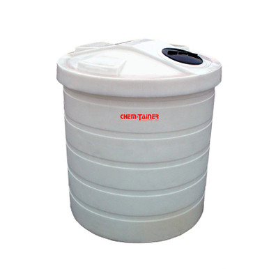
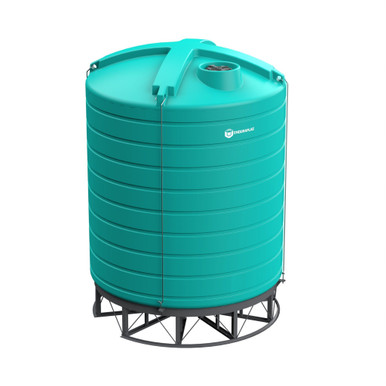
- Vertical bulk tanks with bottom outlets sized for the transfer flow rate. Reference N-40164 5000 gallon Norwesco vertical and N-43128 10,000 gallon Norwesco vertical for the bulk-storage end of the chemical-distribution envelope. Both XLPE construction with 2-inch and 3-inch outlet options that match standard tanker discharge fittings.
- Snyder Industries XLPE Captor double-wall tanks for chemistries where SPCC secondary containment integrates with the loadout pad containment. Reference SII-1006600N42 10,000 gallon XLPE Captor. The double-wall tank construction reduces the credible spill scenarios at the tank itself; the loadout pad still needs the engineered containment for the transfer event.
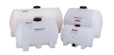
- 1000 gallon bulk water tanks for water-side loadout applications. Reference N-41500 1000 gallon for potable-water and irrigation applications where the loadout pad complexity reduces to drainage geometry without chemical containment.
The procurement conversation should include the loadout pad design as part of the tank specification scope. The tank inlet location and elevation, the outlet location for any outbound transfer events, the freeboard available for surge protection, and the venting design all interact with the pad layout. List pricing for the tanks is on the BC product page; LTL freight to your ZIP and the loadout pad civil construction are separate engineered scopes with separate quotes. Reference the freight estimator or call 866-418-1777.
9. Operational Discipline: The Procedures That Keep the Pad Working
The engineered pad is necessary but not sufficient. The operational procedures around the pad are the other half of the spill-prevention story:
- Pre-transfer inspection checklist. The operator walks the pad before the tanker arrives: drain valve closed, sump empty, spill kit complete, eye-wash flowing, fire extinguisher inspected, communication device functional. The checklist takes 3-5 minutes and prevents the transfer from beginning with a known equipment deficiency.
- Tanker connection inspection. Hose condition, fitting torque, gasket integrity, bonding-and-grounding for flammable chemistries. The connection inspection is the operator's last opportunity to catch a leak before product flows.
- Transfer monitoring. The operator stays at the pad during transfer; remote-monitor designs that allow the operator to leave the pad while the transfer is in progress are not consistent with API 2350 overfill-protection expectations and not consistent with the spill-response time targets.
- Post-transfer inspection. Hose disconnect with proper drain procedure, fitting cap replacement, sump check for any drips or leaks, drain valve verification before the operator releases the tanker.
- Periodic pad inspection. Monthly walkdown of the pad surface, curb integrity, sealer condition, drainage trough cleanliness, equipment stationing. Annual third-party SPCC inspection where required by the regulatory program.
The procedure documentation lives in the site SPCC plan and the standard operating procedures for chemical handling. The procedures need to be specific to the pad geometry and the contained chemistries; generic templates from corporate or from a chemical-association handbook are starting points, not finished documents.
10. The Civil Engineering Conclusion
The loadout pad is the engineered work that prevents the routine transfer event from becoming a regulatory event. The two-grade pad with centerline trough drains rainfall to a permitted discharge while channeling spills to a contained sump. The perimeter curb sized for the largest credible spill plus design-storm precipitation provides the secondary containment volume. The pad surface treatment matched to the contained chemistries gives the slab the service life that justifies the construction cost. The dust-suppression layered design keeps fugitive emissions inside compliance limits. The operator working clearances make the transfer event safe and efficient. The spill-response equipment stationing makes the response to the unintended event measured in seconds rather than minutes.
The civil-design mistakes that produce the regulatory event are not exotic. Single-slope pads that channel spills to the storm sewer. Curb breaches at the tanker access without deployable spill berms. Sealer chemistries that did not match the contained product. Sump discharge valves that defaulted open during operator absence. None of these mistakes require specialized engineering to prevent; all of them require the discipline to engineer the pad as a system, not as a parking spot.
OneSource Plastics ships the polyethylene tanks that are the destinations for the loadout transfer events across all 5 brands — Norwesco, Snyder, Chem-Tainer, Enduraplas, Bushman — with fitting layouts, dimensional drawings, and freeboard documentation that the civil engineer needs to design the pad geometry around. List pricing by SKU is on the product page; LTL freight to your ZIP is quoted separately via the freight estimator or by phone at 866-418-1777. For related operations engineering see secondary containment requirements and tank foundation guide.
Recommended Tanks for This Guide
Live pricing, updated automatically · estimate freight to your ZIP.