Tank Spillover Redundancy Engineering: High-Level Alarm Architecture, Automatic Cutoff Valve Selection, Double-Block-and-Bleed Discipline, and the Layered-Safeguard Design That Stops Loadout Releases Before They Reach the Containment Berm


A bulk tank fills from a tanker truck, a transfer pump, or a pipeline at flow rates that can move several thousand gallons in minutes. The operator on the loadout pad watches the level rise. The fill is supposed to stop at the high-fill setpoint. The level transmitter is supposed to hand off to the alarm. The alarm is supposed to trigger the cutoff valve. The cutoff valve is supposed to close before the tank overfills. Each link in this chain has a probability of failure, and the consequences of a failure that propagates through the entire chain are a chemical release on the loadout pad, an excursion into the secondary containment, environmental reporting, customer trust damage, and operator injury risk if the chemistry is hazardous.
The single-point-of-failure spillover protection design relies on one transmitter, one logic path, and one valve. Any failure anywhere in that chain produces a release. The redundant spillover protection design layers independent safeguards so that no single component failure can produce a release. This article walks the engineering of that layered architecture for bulk polyethylene tank installations across the 5-brand catalog of Norwesco, Snyder, Chem-Tainer, Enduraplas, and Bushman tanks. The references are API RP 2350 for overfill protection at petroleum loadout, ANSI/ISA 84.00.01 for safety instrumented system design, the OSHA 1910.106 process safety management framework where applicable, and field operations data from large bulk-storage facilities operating without spillover incidents over multi-decade service.
1. The Spillover Failure Mode and Why Single-Layer Protection Fails
The spillover event is a chain of failures, not a single failure. Tracing a real spillover backwards from the release event reveals the chain:
- The release on the pad. Chemistry exits the tank top vent, the overflow line, or splashes from an open hatch as the tank is overfilled.
- The cutoff valve did not close. The valve actuator failed to receive a close signal, or received the signal but the valve did not move (mechanical failure), or the valve closed but a check valve downstream failed and product backed up through the closed valve.
- The high-level alarm did not trigger the cutoff signal. The alarm logic did not see a high-level state, or saw it but the relay or output failed.
- The level transmitter did not report the high-level state. The transmitter reading drifted, was reading a wrong level due to scale buildup or fouling, or was disconnected, frozen, or otherwise non-functional.
- The operator did not catch the situation manually. The operator was distracted, was relying on the automation, or was not present at the loadout pad during the fill.
Each link in the chain has a probability of failure during any individual fill operation. Level transmitters fail at perhaps 1 in 5000 fills (drift, fouling, electrical fault). High-level alarms fail at perhaps 1 in 10,000 (logic fault, relay failure). Cutoff valves fail at perhaps 1 in 5000 (actuator, mechanical, check-valve interaction). Operator situational awareness fails at perhaps 1 in 200 fills (distraction, multitasking, schedule pressure). The chain failure that produces a release is the joint probability of all links failing in the same fill operation. Single-layer protection is essentially the operator-only chain, and the 1-in-200 operator failure rate produces release events at a rate that is unacceptable for any chemistry of consequence.
The redundant architecture replaces the single chain with parallel chains. Two independent transmitters report level. Two independent alarm logic paths process the readings. Two independent cutoff valves can stop flow. The operator is present and provides the human cross-check. The joint probability of all parallel chains failing simultaneously is the product of individual failure rates, which drops the release probability by orders of magnitude per layer added. Three layers (transmitter redundancy, alarm logic redundancy, valve redundancy) plus the operator produces a release probability below 1 in 10 million fill operations, which is the demonstrated reliability of well-engineered loadout systems at large bulk-storage facilities.
2. Level Transmitter Redundancy Architecture
The transmitter layer is the first parallel chain. Two transmitters, on independent technologies, with independent failure modes, mounted on independent process connections:
- Primary transmitter: continuous level (radar, ultrasonic, or hydrostatic pressure). The continuous reading drives the level indication on the operator panel and feeds the high-level alarm logic. Reference manufacturer guidance for transmitter selection on the specific chemistry; radar handles high-vapor-pressure service well, hydrostatic handles foam well, ultrasonic is mid-cost for non-foaming aqueous chemistry.
- Secondary point-level switch: high-high alarm. A point-level switch (vibrating fork, capacitance probe, conductive probe) installed at a higher elevation than the high-level setpoint. The switch is an independent device on independent wiring with an independent failure mode from the continuous transmitter. When the continuous transmitter drifts low (reads 80 percent when actual is 95 percent) the secondary switch still triggers when actual level reaches the switch elevation.
- Independent process connections. The two devices mount on different tank fittings. The continuous transmitter on the side or top connection serving normal operation; the point-level switch on a separate top connection. Common fitting failure (gasket leak, blocked nozzle, scale buildup) does not affect both devices simultaneously.
- Cross-check during fill. The control logic compares continuous transmitter reading against the point switch state. If the continuous reading is below the switch elevation but the switch shows triggered, the logic flags the discrepancy as transmitter fault and uses the switch as authoritative.
The dual-redundant transmitter layer increases the level-reading reliability from approximately 99.98 percent per fill to approximately 99.99996 percent per fill. The numerical improvement is small at the per-fill level; the cumulative improvement across a year of multiple-fill operations is the difference between one transmitter-driven near-miss every few months and effectively zero transmitter-driven near-misses across the multi-year operational record.
3. The High-Level Alarm Logic and Independent Trip Path
The alarm logic is the second parallel chain. The continuous level reading flows into normal control logic and into a separate high-level alarm logic path:
- Process control logic. The PLC or DCS reads the continuous transmitter, compares against the high-fill setpoint, and signals the cutoff valve. This path handles normal operation including fill stop at the setpoint, low-level alarms, and routine inventory tracking.
- Independent safety logic. A separate logic device (a safety PLC, a relay-based hard-wired logic, or a dedicated alarm panel) reads the point-level switch and triggers an independent high-high alarm and an independent cutoff signal. The safety logic does not share processor, power supply, or wiring with the process control logic. A failure in the process PLC does not propagate to the safety logic.
- Hard-wired alarm to operator. A high-high alarm produces an audible and visual alarm at the loadout pad and at the control room. The alarm is independent of the process control display; if the process display is frozen or the operator is not looking at it, the alarm still attracts attention. Audible alarm is loud enough to be heard over loadout-pad ambient noise; visual alarm is a flashing beacon visible from the loadout work area.
- Reference voted logic for hazardous service. For chemistries with significant consequence (hydrofluoric acid, anhydrous ammonia, severe-hazard service), implement 2-of-3 voted logic with three independent transmitters. Two of three must report high-level before the trip; this prevents nuisance trips from a single faulty transmitter while still providing redundancy for transmitter failure detection. Reference IEC 61511 for the safety integrity level analysis.
The independent alarm logic adds a parallel decision path. A failure of the process PLC does not prevent the safety logic from acting. A failure of the safety logic still leaves the process PLC handling normal control. Both layers must fail simultaneously to defeat the alarm chain, and the joint failure probability is approximately 1 in 100 million per fill.
4. Double-Block-and-Bleed Cutoff Valve Architecture
The cutoff valve layer is the third parallel chain. The double-block-and-bleed valve arrangement places two valves in series with a vent between them:
- Primary block valve. The first valve in the line stops flow under normal control. Closes on the high-level signal from the process PLC. Sized for the loadout flow rate with appropriate pressure rating for the chemistry. Typically a quarter-turn ball valve with pneumatic or electric actuator and a fail-safe spring return that drives the valve closed on loss of signal or loss of motive power.
- Secondary block valve. The second valve in the line, downstream or upstream of the primary, stops flow as a backup. Closes on the high-high signal from the independent safety logic. Same sizing and pressure rating as the primary. Different actuator power source where practical (one electric, one pneumatic) so that a single utility loss does not affect both valves.
- Bleed valve between blocks. A small drain valve in the pipe section between the two block valves vents trapped chemistry to a containment pan or back to the source. When both blocks close, the bleed valve relieves pressure in the trapped section and confirms that both block valves have indeed closed by allowing pressure to dissipate. A pressure transmitter on the bleed line shows zero pressure if both blocks are sealing; non-zero pressure indicates that one block is leaking past.
- Independent actuator power and signal. Each block valve has independent power and signal wiring so that a single fault does not affect both. Both valves have local position indication (limit switches confirming open or closed state) wired back to the control system.
- Periodic stroke testing. Each valve is stroke-tested on a schedule (monthly or quarterly) to verify operation. The stroke test cycles the valve from open to closed and confirms position feedback. Valves that fail to stroke are replaced or repaired before the next loadout.
The double-block arrangement requires both valves to fail in order for chemistry to flow past the closed-valve barrier. The probability of simultaneous failure on independently powered, independently signaled valves of different actuator types is approximately 1 in 25 million per fill. Combined with the alarm-logic redundancy and the transmitter redundancy, the layered system produces a demonstrated release probability below 1 in 10 billion per fill, which is the engineering target for hazardous-service loadout protection.
5. Field Layout and Mechanical Design Detail
The architecture is correct only if the field installation matches the design. Mechanical layout failures can defeat the engineered redundancy:
- Transmitter mounting at independent fittings. The continuous transmitter and the point-level switch must mount on different process connections. Mounting both on a common nozzle or a common manifold creates a single failure point in the connection itself. Inspect the as-built piping isometric to confirm independent mounting.
- Wiring routing on independent paths. The transmitter wiring and the point-switch wiring should not share conduit or cable tray. A single conduit damage event (rodent, mechanical impact, thermal damage) can disable both circuits if they are co-routed. Run the safety circuit in independent conduit.
- Power supply independence. The process PLC and the safety logic should run on independent power supplies. A common UPS or a common circuit breaker is a single failure point. Use independent UPS feeds or dedicated breaker per system.
- Block valve orientation and spacing. The two block valves should be in series with adequate spacing for inspection, isolation, and bleed valve installation. A common pipe spool with both valves bolted directly together does not allow individual valve maintenance and complicates the bleed-valve geometry.
- Tank top access for sensor maintenance. Both transmitters need maintainable access. A walking platform on the tank top, removable sensor heads, and adequate cable length for sensor replacement without de-tanking the entire vessel. Reference N-43128 10,000 gallon Norwesco vertical for the bulk tank envelope where this access matters most. List pricing on the product page; LTL freight to your ZIP via the freight estimator or by phone at 866-418-1777.
- Containment under valves and tank vent. Even with redundant protection, a release can occur from upstream piping rupture, loadout-hose failure, or vent overflow during severe upset. The secondary containment under the loadout area must be sized for the credible release volume per local code (typically the volume of the largest connected vessel plus precipitation freeboard).
The field layout audit happens during commissioning and at every major maintenance turnaround. As-built drawings are reviewed against the design intent; deviations are documented and corrected before the system returns to service.
6. Operator Training and the Human Layer
The redundant automated system does not replace the operator; it backs up the operator and the operator backs up it. The human layer is the cross-check that catches automation failures the system itself may not detect:
- Operator at the loadout pad during every fill. Not in the truck cab, not at the control room, but physically at the pad with line-of-sight to the tank, the loadout connections, and the local panel. The operator presence is a documented operational requirement, not a discretionary practice.
- Pre-fill checklist. Before starting the fill, the operator verifies tank current level, available capacity, valve lineup, hose connection, leak inspection at all connections, transmitter readings agree across both devices, alarm panels show ready state, and emergency shutoff is accessible.
- Mid-fill monitoring. The operator watches the level rise rate against expected fill time. A faster-than-expected rise signals a transmitter reading error or unexpected flow rate. A slower-than-expected rise signals a partially closed valve or a leak. Either anomaly triggers manual investigation and potential abort.
- End-of-fill verification. When the fill stops at the setpoint, the operator confirms tank level reading, confirms cutoff valve position (closed limit switch), inspects all connections for any drips or seepage, and documents the completed fill in the operating log.
- Emergency shutoff knowledge. The operator knows the location and operation of every shutoff valve in the loadout system. Manual shutoff is the final recourse if the automated system has not stopped flow when expected. The operator practices the shutoff procedure at scheduled drills.
- No-fill conditions. The operator knows the conditions under which a fill is not authorized to proceed: failed alarm test, failed valve stroke test, missing PPE, weather conditions outside allowed envelope, or any system anomaly that has not been resolved. The fill is delayed until the no-fill condition is cleared.
The operator is the layer that catches what the automation cannot. Software and instrumentation can fail in ways the design did not anticipate; the trained operator standing at the pad sees the actual physical situation and intervenes if reality does not match expectation. The combined human-and-automation system reaches reliability that neither layer can reach alone.
7. Tank Selection That Supports Layered Spillover Protection
The tank itself supports or hinders the spillover-protection installation. Selection criteria for a redundant-protection-ready tank:
- Multiple top fittings for independent transmitter mounting. The tank top should provide at least three threaded or bolted fittings: one for the continuous transmitter, one for the point-level switch, one for the vent. Tanks with limited top fittings force shared mounting that defeats the redundancy. Reference N-40164 5000 gallon Norwesco vertical for the bulk envelope with adequate fitting count.
- Hatch access for internal inspection. A hatch large enough for a person to enter (with confined-space procedures) supports inspection of the internal probe surfaces and verification that the probe hardware is in proper orientation. Smaller hatches at least allow remote camera inspection.
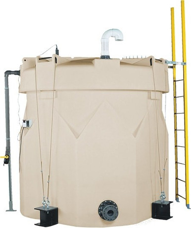
- Vent sized for emergency relief. The vent must handle the worst-case fill rate. If both block valves fail to close, the vent is the last barrier between overfill and release. An undersized vent does not prevent release in this scenario; an oversized vent provides margin. Reference SII-1006600N42 10,000 gallon XLPE Captor double-wall for the engineered-vent envelope.
- Double-wall tank for inherent secondary containment. A double-wall tank provides containment integrated with the primary tank and removes the need for separate containment berm engineering. The interstitial space accommodates leakage from the primary and supports interstitial-monitoring as an additional safeguard layer.
- Heavy-duty fittings rated for repeated cycling. The transmitter and point-switch fittings see periodic removal for maintenance. Heavy-duty fittings (stainless or reinforced threaded) outlast standard fittings under repeated wrench cycles. Reference N-41524 2500 gallon for the mid-volume bulk envelope.
The tank specification choices set the upper bound for the protection system that can be built around it. List pricing on each product page; LTL freight to your ZIP via the freight estimator or by phone at 866-418-1777.
8. Periodic Testing and Continued Reliability
The redundant architecture maintains its reliability only if the layers are tested and confirmed periodically. The test program:
- Monthly alarm test. Manually trigger each transmitter and each point switch into alarm state. Confirm the alarm logic responds correctly, the operator panel displays the alarm, the audible and visual indicators activate, and the cutoff signal reaches the valve.
- Quarterly valve stroke test. Cycle each block valve through full open and full close. Confirm position feedback at both ends of travel. Verify the bleed valve operation between blocks.
- Annual full-system functional test. Simulate a complete fill operation up to and through the high-level trip. Confirm the alarm cascade triggers all expected outputs, the cutoff valves close in the expected sequence, the operator panel logs the event, and the system returns to ready state on reset.
- 5-year sensor calibration. Continuous transmitters and point switches drift over time. Re-calibrate against a known reference (level standpipe, traceable distance reference, or factory-traceable test fluid) and document the as-found and as-left readings. Replace devices that cannot calibrate within the manufacturer specification.
- Documentation and trending. Every test result is documented and trended. Slow drift, increasing test failures, or unexpected behavior triggers proactive replacement before the device fails in service.
The reliability of the layered system is not static. Devices age, gaskets relax, software updates may change behavior, and the operating environment changes over time. The test program detects the change and the maintenance program corrects it before the change degrades the protection.
9. The Spillover Redundancy Conclusion
Single-layer spillover protection produces release events at rates that are unacceptable for hazardous-service bulk loadout. Layered protection with redundant transmitters, independent alarm logic, double-block-and-bleed cutoff valves, and a present trained operator produces release rates orders of magnitude lower and approaches the demonstrated reliability of well-engineered loadout systems across decades of operation.
The engineering effort to design and install the redundant architecture is real. The capital cost is several times higher than single-layer protection. The maintenance burden is higher with periodic testing of every layer. The benefit is the avoided release events: the avoided environmental reporting, the avoided customer trust damage, the avoided operator injury, and the avoided regulatory consequences. For chemistries with significant consequence, the redundant architecture is not optional; it is the engineering standard that responsible operators implement.
OneSource Plastics ships polyethylene bulk tanks across all 5 brands of Norwesco, Snyder, Chem-Tainer, Enduraplas, and Bushman with the fitting count and the dimensional envelope that support layered spillover protection installation. The protection-system engineering is done by the customer site engineer with reference to API RP 2350, ANSI/ISA 84.00.01, and applicable local code. List pricing on each product page; LTL freight to your ZIP via the freight estimator or by phone at 866-418-1777. For related operations engineering see secondary containment requirements and tank specification sheet reading.
Recommended Tanks for This Guide
Live pricing, updated automatically · estimate freight to your ZIP.