Tank-to-Tank Manifold Engineering for Redundant Feed Systems: Three-Way Valves, Tee Fittings, Isolation Architecture, and the Swing-Batch Discipline That Eliminates Process Downtime During Tank Cleaning


Single-tank chemical feed systems have a built-in vulnerability: when the tank needs to come out of service for cleaning, inspection, chemistry change, or replacement, the downstream process stops. For a fertilizer dealer's UAN injection during planting season, for a wastewater plant's polymer feed during a storm event, for a metal-finishing line's caustic dosing during a critical batch, the cost of process downtime substantially exceeds the cost of installing a redundant tank with a properly engineered manifold. The manifold engineering is the load-bearing element of the redundancy story; the tanks themselves are the easy part. This article walks the architecture decisions that separate a manifold that delivers true redundancy from one that just adds piping cost.
References: ASME B31.3 Process Piping for non-flammable chemical service; ASME BPE for sanitary tank-to-tank transfers in food and pharma; ANSI/ASSE 1057 dual-check valve design; ISA S5.1 instrumentation and controls symbology; manufacturer technical bulletins from Snyder, Norwesco, Chem-Tainer, and Enduraplas on tank fitting hardware. The valve selection guidance below cross-references Hayward, GF Piping Systems, Asahi/America, and Plast-O-Matic spec sheets for industrial polyethylene and PVC valves rated for tank-side service.
1. What Redundancy Actually Means in Tank Service
Redundancy is a slippery word in process design. It can mean any of several things:
- N+1 capacity redundancy: two tanks that together exceed the demand by 100 percent or more, with either tank capable of carrying full demand alone for a defined window. This is the right architecture when the failure mode is tank-out-of-service for a known-duration cleaning or inspection.
- Hot standby redundancy: two tanks both pressurized and ready, with automatic or rapid manual transfer between them. Used when the failure tolerance is measured in minutes rather than hours.
- Cold standby: primary tank in service, secondary tank installed and piped but empty. Failover requires a fill cycle from supply truck or from the primary's residual contents. Tolerable when downtime tolerance is measured in days.
- Parallel feed: two tanks both contributing to the demand simultaneously, with hydraulic balancing across the manifold. Used when single-tank capacity is insufficient for the peak demand.
- Series buffer: a primary tank feeds a smaller buffer tank that smooths supply variability and provides a small ride-through window. Architecturally similar to redundancy but the failure mode is supply continuity rather than tank availability.
The choice among these affects the manifold architecture in significant ways. N+1 with cold standby uses simple isolation valves and dead-leg piping. Hot standby uses 3-way diverter valves and matched controls. Parallel feed uses balancing valves and matched-orifice runs. The first design decision is to define which redundancy mode the operator actually needs, and not over-design the manifold for a redundancy mode that the application does not require.
2. The Tee-and-Two-Isolation-Valves Pattern
The simplest tank-to-tank manifold for cold-standby or N+1 redundancy:
- Tank A discharge through bulkhead to a tee fitting; one branch of the tee feeds the process, the other branch dead-ends with a capped flushing port.
- Tank B discharge through bulkhead to a parallel tee; same branching.
- The two process branches join at a second tee that delivers to the process pump.
- One isolation valve between each tank tee and the joining tee. Closed isolation valve = tank out of service.
The architecture works for chemistries where the tank fluid is non-stratifying, non-reactive when the two tanks have slightly different concentrations or temperatures, and tolerant of the dead-leg between the closed valve and the joining tee. Most fertilizer service, water service, and dilute-chemistry service falls in this category.
The dead-leg matters. When tank A is in service and tank B's isolation valve is closed, the line from tank B's tee to the joining tee remains full of tank B's chemistry, sitting stagnant. Stagnant chemistry can grow biofilm, can stratify, can scale, and can over time corrode the valve seats. The mitigation is to keep the dead-leg short (under 10 pipe diameters from valve to joining tee), to run a periodic flush sequence, or to use a bleed valve at the joining tee that allows brief flow-through during the standby tank's service period.
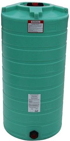
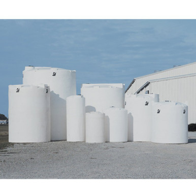
The Norwesco N-40146 1,500 gallon vertical in matched pairs is a common N+1 redundancy configuration for fertilizer dealers; the N-40635 3,000 gallon in matched pairs scales the same architecture for higher seasonal demand.
3. Three-Way Diverter Valve Architecture
For hot-standby redundancy where transfer between tanks must be fast and the dead-leg cannot be tolerated, the three-way diverter valve replaces the tee-and-two-valves pattern. A single 3-way valve at the joining point selects either tank A or tank B as the source for the downstream process; the unselected tank is fully isolated with no dead-leg into the live circuit.
Three-way valve selection matters. For tank-to-tank diverter service, the valve needs:
- L-port or T-port configuration matched to the flow pattern. An L-port 3-way diverter routes flow from a single common port to either of two branch ports; this is the typical tank-source-selector use case. A T-port 3-way is used for combining or splitting flows; a different topology that is not the right fit for source selection. Specify L-port for diverter service.
- Material compatibility for the chemistry. PVC for general industrial; CPVC for elevated temperature; PVDF for halogen acids and high-purity service; polypropylene for sodium hypochlorite at moderate temperatures. The valve body and seat materials matter more than the tank material because the valve sees the chemistry under flow, with shear, with cycling.
- Actuation method matched to the duty cycle. Manual ball valves for occasional swap-overs; pneumatic or electric actuators for frequent or scheduled transfers; positioners and feedback for control-loop integration.
- Pressure and temperature ratings 50-100 percent above the operating envelope. Tank-side service is low-pressure but the cycling history shortens valve life; oversize the rating.
Cost ranges: 2-inch PVC manual L-port 3-way valve runs 200-400 dollars; the same valve in CPVC 400-700 dollars; pneumatic actuator adds 600-1500 dollars; PVDF valves run 2-4x the PVC equivalent. The manifold cost on a redundant 2-tank installation is typically 1500-5000 dollars in valves and fittings, comparable to or slightly less than the cost of a single tank.
4. Common Header vs Independent Pump-Per-Tank
The next architecture decision after the diverter valve: do both tanks share a common downstream pump, or does each tank have its own pump? The trade-offs:
Common header with shared pump. Lower capital cost (one pump instead of two). The pump sees variable suction-side hydraulics depending on which tank is selected. The pump's NPSH-available calculation must account for the worst-case suction line length from either tank. A failure of the shared pump takes the entire feed system offline. Re-pumping after a chemistry change requires flushing both the tank and the pump.
Independent pump per tank. Higher capital cost (two pumps). Each pump is dedicated to its tank and has consistent suction-side hydraulics. A failure of either pump leaves the other tank fully operational. Chemistry changes can be performed on one tank-and-pump pair while the other continues service. Better fit for redundancy intent.
The independent-pump architecture is generally the right answer when redundancy is the design goal. The shared-pump architecture is appropriate only when the pump itself is well-maintained and not the failure mode being protected against. For polymer dosing on wastewater treatment, where pump fouling is a more common downtime cause than tank issues, the independent-pump architecture is essentially mandatory.
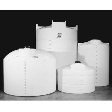
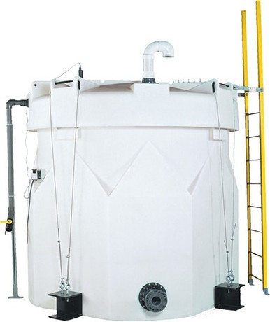
The Snyder SII-5490000N42 1,550 gallon double-wall XLPE in pairs with independent pumps is the standard architecture for redundant polymer feed at municipal wastewater plants; the double-wall geometry adds containment defense-in-depth that single-wall tanks do not provide. The SII-5990102N42 1,000 gallon double-wall is the smaller-footprint version of the same architecture.
5. Manifold Sizing and Hydraulic Balance
The hydraulic design of the manifold ensures that flow from either tank reaches the process at consistent pressure and flow rate, regardless of which tank is selected. The basic principles:
- Symmetric piping. Both tanks should have the same suction line length, same number of fittings, same elbows, same valve count, between bulkhead and joining tee. Asymmetric layout causes asymmetric flow and asymmetric tank-level drawdown when both tanks are in service in parallel-feed mode.
- Pipe sizing for the worst-case flow. Size the suction-side piping to the pump's flow rating with at most 5 ft/s velocity and at most 10 percent of NPSH-available consumed by friction. For tank-side polyethylene piping, this typically means 1.5x to 2x the discharge-side pipe size.
- Slope toward the joining tee. Air-bind avoidance: any high point in the suction line traps air during the standby tank's service, and the trapped air can prevent priming when the tank is selected. Slope the line toward the joining tee at 1/4 inch per foot minimum.
- Drain points at low spots. Drain valves at the lowest points permit flushing the line during chemistry changes and permit complete drainage for cold-weather lay-up.
For manifolds where both tanks contribute simultaneously to the process (parallel feed mode), an additional balancing requirement applies: a globe-pattern balancing valve on each tank's discharge with a flow indicator. The balancing valves are adjusted at commissioning to equalize the contribution from each tank, which equalizes the drawdown rates and lets both tanks be filled and serviced on a synchronized schedule.
6. Isolation for Maintenance: The Lockout/Tagout Discipline
OSHA 1910.147 lockout/tagout applies when a tank is taken out of service for cleaning, inspection, or repair. The manifold has to be designed to support unambiguous isolation that can be verified and locked. The minimum requirements:
- Double-block-and-bleed at every isolation point that protects a worker. Two isolation valves in series with a bleed valve between them. The bleed valve permits verification that the upstream valve is fully closed (no leakage past the closed valve) before any work begins.
- Locks on every isolation valve handle. Padlock through a lockout hasp; the lock identifies the worker who applied it and prevents anyone else from operating the valve.
- Tags on every locked valve. Tag identifies the worker, the date, the work being performed, and the expected restoration date.
- Energy-isolation audit before work begins. A second person verifies that all energy sources (tank chemistry pressure, pump motive force, control air, electrical) are isolated and locked.
- Restoration sequence at end of work. Reverse of isolation, verified by the same second person, with all locks and tags removed before any energizing operation.
The manifold engineering decision: include a bleed valve between every pair of isolation valves so that double-block-and-bleed is physically possible. The cost is one additional valve per isolation point; the value is a manifold that supports the operational discipline rather than fighting it.
7. Cleaning, Sanitization, and Chemistry Change Operations
The manifold's behavior during cleaning operations distinguishes a good manifold from a great one. The capabilities to design in:
Drain-down to the secondary containment dike. The lowest point of the manifold should drain to a sump or to the dike with a positive slope. This permits cleaning operations to push residual chemistry to a known collection point rather than leaving it stranded in the manifold.
Air-blow connection. A quick-disconnect fitting at the joining tee permits compressed air to push the manifold chemistry back to the standby tank or to the dike. The air pressure should be limited (15-30 psig typical) to avoid damaging fittings or creating mist hazards.
Wash-water connection. A second quick-disconnect for clean rinse water. The sequence after chemistry change: drain, air-blow, water rinse, second drain, second air-blow, return to service. The manifold has to physically support the sequence; retrofit cleaning connections are awkward and often skipped.
Sample valve at the joining tee. A small sample valve permits pulling a chemistry sample from either tank's contribution to the process. Used during the chemistry change to verify residual concentration before declaring the changeover complete.
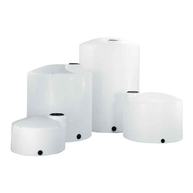
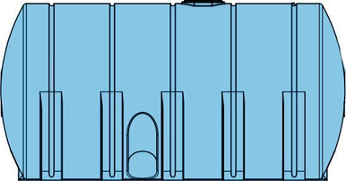
The Enduraplas EP-THV02500FG 2,500 gallon with its dome-mounted accessory ports supports a CIP-friendly manifold architecture; the dome ports can host the air-blow and wash-water connections directly above the tank without interfering with the bulkhead piping. For cone-bottom service where complete drainage is the priority, the Norwesco N-43852 1,000 gallon 45-degree cone-bottom is the geometry-matched companion.
8. Instrumentation and Controls Integration
The manifold's controls integration determines whether the redundancy is operationally trustworthy or merely theoretically present:
- Tank-level transmitters on both tanks. Continuous level reading from each tank into the same control system permits informed switching decisions and supports automated transfer logic. Hydrostatic, radar, or guided-wave radar are the typical choices.
- Position feedback on the diverter valve. The control system must know which tank is selected; open/closed limit switches or a positioner with continuous feedback. Without position feedback, the operator does not know which tank fed the last batch.
- Flow indication downstream of the joining tee. Confirms that the selected tank actually delivered. Flow indication during the changeover catches the failure mode where the new tank's level drops as expected but no flow reaches the process (clogged pickup, closed valve, frozen line).
- Pressure indication at the pump suction. Detects loss of prime, NPSH problems, and air-binding. Critical during the first few minutes after a tank changeover when transient hydraulics destabilize.
- Alarm logic for tank-low, tank-high, transfer-failed, and chemistry-mismatch. The chemistry-mismatch alarm uses a conductivity or pH sensor downstream of the joining tee to detect a wrong-tank-selected error within seconds of the transfer.
The instrumentation cost on a redundant 2-tank installation typically runs 5,000-15,000 dollars depending on complexity. The value is the operational confidence that the redundancy actually works when needed; redundancy that the operator does not trust is redundancy that gets bypassed during the next emergency.
9. Brand-by-Brand Manifold Configuration Notes
- Norwesco vertical pairs for fertilizer or water: standard 2-inch threaded bulkhead with PVC valve trim; manual L-port 3-way diverter at the joining tee. Reference: N-40146 1,500 gallon, N-40635 3,000 gallon.
- Snyder Captor double-wall pairs for chemical service: integrated dome ports support sample valve and wash connection; primary tank annulus monitoring is independent of manifold. Reference: SII-5490000N42 1,550 gallon, SII-5990102N42 1,000 gallon.
- Snyder waste oil pairs: redundancy in waste-oil service is typically driven by collection cycle rather than process continuity; the manifold may use a simpler tee-and-two-isolation architecture with positive-displacement transfer pump. Reference: SII-5740102N95703 275 gallon.
- Enduraplas vertical pairs for industrial: dome-port architecture supports CIP-friendly cleaning manifold. Reference: EP-THV02500FG 2,500 gallon.
- Chem-Tainer vertical pairs: standard threaded bulkhead with PVC trim; suitable for general industrial redundant service. Reference: TC6446IA 500 gallon HDPE.
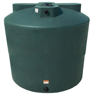
- Bushman water pairs for emergency or fire-suppression reserve: simple isolation manifold with check valves to prevent backflow during fill operations. Reference: BM-WW-1500-GL-NAT 1,500 gallon.
OneSource Plastics quotes complete redundant-tank packages including matched-pair tanks, manifold valves and fittings, instrumentation, and commissioning support. List pricing on a 2-tank Norwesco 1,500-gallon redundant package with manifold and basic instrumentation runs $8,500 and up depending on configuration. LTL freight to your ZIP is quoted via the freight estimator or by phone at 866-418-1777.
For complementary reading, see our secondary containment volume math for the dike sizing that surrounds the redundant tank pair, and our Snyder Captor SPCC walkthrough for the regulatory framing of double-wall containment in a redundant configuration.
Recommended Tanks for This Guide
Live pricing, updated automatically · estimate freight to your ZIP.