Cathodic Protection Rectifier Integration When Polyethylene Tanks Coexist With Steel Pipe Networks: Galvanic Isolation, NACE SP0169 Discipline, and the Stray-Current Failure Modes That Surprise Operators
Cathodic protection (CP) is a corrosion-control discipline designed for buried steel: a rectifier drives DC current from anodes to the protected steel structure, the steel cathode polarizes negatively, and corrosion is suppressed. The math, the standards (NACE SP0169 covers the bulk of it), and the operating practice all assume metallic structures connected by metallic pipe and protected by an integrated CP system. When a polyethylene tank gets installed alongside a steel pipe network at the same facility, several things change at once. The poly tank is electrically nonconductive, so it does not need CP and does not participate in the polarization. The metallic piping connected to the poly tank still needs CP if buried. The transition fittings between poly and steel become galvanic-isolation points whether by accident or by design. And stray current from a poorly maintained rectifier can damage adjacent buried metallic infrastructure or create unexpected ground potentials at the polyethylene tank pad. This article is the operator-level guide to getting the integration right.
References: NACE SP0169 (now AMPP SP0169-2013) Standard Practice for Control of External Corrosion on Underground or Submerged Metallic Piping Systems; NACE SP0285 Corrosion Control of Underground Storage Tank Systems by Cathodic Protection; ASME B31.4 Pipeline Transportation Systems; ASME B31.8 Gas Transmission and Distribution; OSHA 1910.106 atmospheric storage tanks; and the manufacturer's transition-fitting documentation from Norwesco, Snyder, and Chem-Tainer for poly-to-steel piping interfaces. The voltages, currents, and ground-potential thresholds quoted below come from these sources.
1. Why Polyethylene Tanks Do Not Need Cathodic Protection
Cathodic protection works by driving electrons into a metallic structure from an external power source so that the metal surface becomes a cathode and corrosion (which is metal oxidation, an anodic process) is thermodynamically suppressed. The mechanism requires a metallic substrate that can conduct electrons from the protection current source to every surface that contacts the corrosive environment. Polyethylene is an insulator with electrical resistivity approximately 10^16 ohm-cm, which is 22 orders of magnitude higher than carbon steel. CP current cannot flow through the tank wall, no electrons are delivered to any potentially corroding surface, and the protection mechanism does not apply.
This is not a limitation of polyethylene; it is the reason polyethylene tanks are specified in the first place. The tank wall is not corroding because the failure modes of polyethylene (ESC, oxidation, mechanical fatigue) are entirely different from the metal-loss failure modes of steel. The CP system protecting the buried steel piping does not need to extend to the polyethylene tank because the polyethylene tank does not need it.
The mistake that operators occasionally make is to assume that because the steel piping is on a CP system, the connected polyethylene tank is somehow protected by the same system, or alternatively that the polyethylene tank somehow disrupts the CP system. Neither is true. The polyethylene tank is electrically isolated from the CP circuit at the moment the polyethylene wall begins. The system architecture has to be designed around that fact.
2. Where the Galvanic Boundary Falls and Why It Matters
The galvanic boundary in a polyethylene-tank-with-steel-piping installation falls at the threaded transition fitting between the poly tank bulkhead and the steel pipe nipple. On a typical installation, the bulkhead is a polyethylene-or-PVC threaded fitting molded into or installed through the tank wall; the first metallic component is the steel or stainless steel pipe nipple threaded into the bulkhead's interior threads. The interior of that nipple is wetted by the stored chemistry; the exterior is exposed to atmosphere or to the tank pad's containment dike.
From the CP system's perspective, this transition is a perfect natural galvanic isolator. No metallic path crosses from the buried steel piping (CP-protected, polarized to a known potential like -850 mV vs Cu/CuSO4) through the tank wall to anywhere else. The CP current does not need to extend past the transition. As long as the buried steel inlet and outlet piping each have their own complete CP coverage all the way to the transition fitting, the system is well-designed.
The mistake that creates problems is when an operator installs a metallic supplemental support around the tank exterior - a steel saddle, a metallic strap, an electrical-bonded grounding clamp - and inadvertently creates a metallic path between two different sections of the steel piping network, with the polyethylene tank in the middle. The two steel sections may have different CP polarization levels (different rectifier outputs, different soil resistivity, different anode bed proximity), and the metallic bypass shorts them together at a non-zero current. Stray current flows around the polyethylene tank, and unexpected anodic dissolution can occur at whichever steel section sees higher exit current density. The fix is to electrically isolate any metallic tank-mounting hardware from both sections of the buried piping network.
3. Insulating Joints and Where to Place Them
Insulating joints (sometimes called dielectric unions or insulating flanges) are mandatory whenever a CP-protected metallic piping section needs to terminate at a non-protected component. The placement rule from NACE SP0169 and from utility-industry CP design practice: install an insulating joint at every transition between protected metallic structure and non-protected metallic structure, at every transition between metallic and non-metallic piping, and at every above-grade exit of an underground CP-protected metallic line.
For a polyethylene-tank-plus-steel-piping installation, the practical implementation:
- Insulating union immediately upstream of the tank inlet bulkhead. The CP-protected buried inlet line terminates at this union; the steel nipple between the union and the bulkhead is a short atmospheric-exposure section that does not need CP. The union prevents any future bonding or grounding modification from extending CP current into the tank-pad area.
- Insulating union immediately downstream of the tank outlet bulkhead. Symmetric to the inlet. The metallic outlet piping that goes back underground is on its own CP coverage starting at the union.
- No insulating joint required at the bulkhead-to-tank-wall interface. The polyethylene-to-metallic transition is a natural insulator; it is a galvanic boundary by construction.
- Bonding wire across the insulating joint with a surge protector. NACE SP0169 recommends a 0.5-2 kA surge protector across each insulating joint to handle lightning and switching transients without breaking through the dielectric. Without the surge protector, a near-strike lightning event can arc across the insulating joint and damage both the joint and the CP system.
The total hardware cost per transition is 200-500 dollars depending on pipe size and material. The labor is 1-2 hours per joint. The downside of skipping the insulating joints is that any future facility change (a new ground rod, a new metallic structure tied into the piping network, a new pump or skid) can create a stray-current path that takes years to manifest as a corrosion failure on an unrelated steel section.
4. Stray Current From Adjacent Rectifiers
A failure mode that polyethylene-tank operators do not always anticipate: an adjacent facility's CP rectifier can drive stray current through the soil under the tank pad. The soil is the return path for the protection current, and high-current rectifiers (50-200 amps) drive measurable soil potentials over a radius of hundreds of feet. Any metallic structure in that soil that is not part of the protected system - tank-pad rebar, pipe support stands, electrical conduit, ground rods - can become an unintended pickup point. Current enters the metallic structure from one side and exits from the other; the exit point sees accelerated corrosion.
For a polyethylene tank installed near a CP rectifier (within 500 feet, particularly within line-of-sight along a conductor corridor):
- Ground potential survey before construction. Measure soil-to-Cu/CuSO4 reference potentials at the planned tank-pad locations across multiple seasons. Variations over 200 mV across the tank footprint indicate active stray-current activity.
- Tank-pad rebar bonding decision. If the pad rebar is to be bonded to a ground rod, the ground rod should not be installed in a high-gradient stray-current zone. If the pad is in a stray-current zone, consider an unbonded (floating) rebar mat to avoid creating a pickup.
- Drainage bond on existing nearby metallic structures. A drainage bond (a low-resistance wire connecting two metallic structures across a stray-current gradient) can equalize potentials and protect both. Coordinate with the rectifier owner; this is a community of practice across facilities.
- Re-survey after construction. Verify that the as-built tank-pad ground potentials match the design intent. Discrepancies are usually traceable to construction-phase metallic items (forgotten rebar tie wires, temporary grounding cables, abandoned conduit) that need to be either removed or bonded into the equalization scheme.
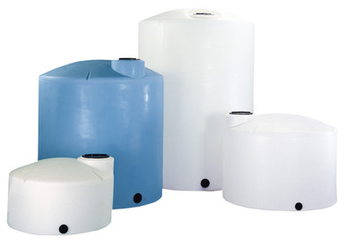
The Snyder SII-5490000N42 double-wall and SII-5990102N42 1,000 gallon double-wall XLPE tanks are common selections for installations adjacent to CP-protected steel infrastructure because the double-wall geometry provides leak-detection independence from any soil-conductivity question. The Norwesco N-40635 3,000 gallon single-wall is the lower-cost selection for service that does not require double containment.
5. Reading Rectifier Output and Verifying CP Effectiveness
Even when the polyethylene tank does not need CP, the operator still needs to understand the rectifier readings on the connected metallic piping to verify that CP is working as designed. The basic readings:
- Rectifier output voltage: typically 10-50 V DC. The exact value depends on the soil resistivity and anode bed design. Routine drift over 20 percent indicates anode bed deterioration or soil-resistivity change.
- Rectifier output current: typically 5-50 A DC for a small commercial system, scaling to 100-500 A for large pipeline systems. Current dropping over time at constant voltage indicates increased circuit resistance, usually from anode consumption.
- Pipe-to-soil potential at the protected structure: measured with a Cu/CuSO4 reference electrode. The 850 mV criterion (pipe-to-soil more negative than -850 mV vs Cu/CuSO4) is the most common protection threshold from NACE SP0169 §6.2.2. Polarization-shift criteria (100 mV negative shift from native potential) are alternatives.
- Coupon current readings if installed: coupons are small steel samples buried alongside the protected piping with their own dedicated lead. Reading the coupon current periodically gives a direct measure of CP delivery.
For the polyethylene tank in the network, none of these readings apply to the tank itself; they apply to the steel sections feeding and draining the tank. The tank-pad operator should still log them at quarterly cadence because changes in the readings can signal stray-current changes that affect the tank pad.
6. Soil-Side vs Process-Side Corrosion: A Common Confusion
NACE CP discipline addresses external (soil-side) corrosion of buried metallic piping. It does nothing for internal (process-side) corrosion of the same piping. When chemistry inside a steel pipe attacks the steel from the inside, the failure mode looks identical to a CP failure from the outside but the diagnosis and remediation are completely different.
For polyethylene-tank installations, the process-side chemistry was the reason the tank itself was specified as polyethylene. The connected steel piping is exposed to the same chemistry on the inside, and unless the operator made a deliberate choice to use polyethylene-lined pipe, fluoropolymer-lined pipe, or a corrosion-resistant alloy, the steel piping is corroding from the inside on the same schedule that a steel tank would have been. CP does not help. The remediation is to replace the steel piping with a corrosion-resistant material (CPVC, polypropylene, lined steel, Hastelloy, etc.) or to live with a known-finite service life on the steel piping.
This is the real argument for converting from steel piping to polyethylene-lined or all-plastic piping when a polyethylene tank is being installed. The tank decision is half the corrosion-control story; the piping decision is the other half. Operators who treat the two decisions separately end up with a long-lived tank piped with corroding steel that becomes the limiting failure mode of the system.
7. Lightning, Surge, and Bonding Around the Tank Pad
NFPA 780 §7.6 and Annex N cover lightning protection on aboveground storage tanks. For polyethylene tanks specifically, the standard recognizes that the tank wall does not provide a path for lightning current; the protection scheme has to provide an alternative path. The approach combines:
- Lightning rod (air terminal) on a mast adjacent to the tank. The rod intercepts the strike and conducts to ground via a down-conductor and ground rod system. The mast height has to provide a 30-meter or 45-meter rolling-sphere protection radius depending on the protection level.
- Bonding of all metallic accessories on or near the tank. Ladder, fill-pipe, mounting brackets, electrical conduit, and any associated CP-isolated metallic structures need to be bonded to a common low-impedance ground at the tank pad. Bonding prevents step-and-touch potential during a strike.
- Surge protection on every electrical conductor entering the tank-pad area. Power, signal, and instrumentation lines all need surge suppression at the building entry and at the tank-pad equipment. The surge protectors operate in parallel with the bonded grounds and clamp transient voltages to safe levels.
The CP system needs to be designed compatibly with the lightning protection system. The same insulating joints that prevent CP stray-current bypass also prevent lightning current bypass; the surge protectors across the insulating joints are the deliberate path that handles the lightning event without breaking the CP isolation. Coordinate the two designs at the engineering stage; do not let one come in retrofit on top of the other.
8. Documentation and Maintenance Cadence
The CP-and-polyethylene-tank documentation package that the facility engineer should maintain:
- System single-line drawing showing all metallic structures, all insulating joints, all CP rectifiers and anode beds, and the polyethylene tank and its bulkhead-to-pipe transitions. The drawing is the reference for any future work that touches the system.
- Insulating-joint location list with installation dates and surge-protector ratings. Joints get re-tested at 5-year intervals; surge protectors get visually inspected annually and replaced after any documented strike event.
- Quarterly rectifier-output log: voltage, current, on/off potentials at standard test stations. The log identifies drift trends before they become protection failures.
- Annual close-interval potential survey: measure pipe-to-soil potential every 5-10 feet along the buried piping route. The survey identifies localized protection deficiencies that the test-station readings miss.
- Stray-current investigation if any reading drifts more than 100 mV from baseline. The investigation may identify a new metallic structure (tank or otherwise) that has been added to the network without proper isolation.
The polyethylene tank itself does not appear in most of these readings, which is exactly what the operator should expect. The discipline is to make sure the polyethylene tank does not silently disrupt the CP system by acting as a galvanic-isolation surprise, and the way to ensure that is to design the isolating joints in deliberately at the start.
9. Brand-and-Configuration Notes for CP-Adjacent Installations
- Norwesco vertical with steel piping network: standard threaded bulkhead on the tank, insulating union at the steel side immediately downstream. Reference: N-40146 1,500 gallon, N-40164 5,000 gallon.
- Snyder Captor double-wall in CP-adjacent service: annulus monitoring complements CP discipline by providing an independent leak-detection layer; either the CP system or the annulus would catch a fitting failure. Reference: SII-5490000N42 1,550 gallon.
- Snyder waste oil double-wall: waste oil chemistry is mildly corrosive to carbon steel; insulating joints upstream and downstream are mandatory if any buried steel piping connects. Reference: SII-5740102N95703 275 gallon.
- Enduraplas vertical for fertilizer or industrial water: standard threaded bulkhead; specify SS304 or SS316 nipple at the bulkhead-to-pipe interface for chloride-bearing chemistries. Reference: EP-THV02500FG 2,500 gallon.
- Bushman water-only: water service in CP-adjacent installations: standard insulating union; PVC piping downstream is the cheapest option. Reference: BM-WW-1500-GL-NAT 1,500 gallon.
OneSource Plastics quotes complete tank-and-piping packages including insulating joints, surge protectors, and SS pipe nipples. List pricing on a 1,500-gallon Norwesco vertical with poly-to-steel transition kit runs $2,400 and up depending on configuration. LTL freight to your ZIP is quoted via the freight estimator or by phone at 866-418-1777.
For complementary reading, see our secondary containment volume math for the dike sizing that goes around the tank pad, and our lightning protection guide for the bonding scheme that integrates with CP discipline.
Recommended Tanks for This Guide
Live pricing, updated automatically · estimate freight to your ZIP.