HDPE Pipe to Tank Flange Transition Engineering for Buried Piping Runs: Heat-Fusion vs Mechanical-Joint Selection, Thrust Restraint, Settlement Accommodation, and Buried-Service Inspection Discipline
The transition from a buried high-density polyethylene (HDPE) piping run to a polyethylene storage tank is one of the most failure-prone interfaces in industrial water and chemical systems. The buried HDPE pipe is engineered for thermal expansion, ground settlement, and freeze-thaw cycling through its flexibility and joint geometry; the polyethylene tank is engineered for stationary loading at a fixed foundation. The transition between the two must accommodate the pipe motion without transmitting stress to the tank shell, must seal against the operating pressure and temperature, must resist thrust at every direction change, must remain inspectable across the buried service life, and must be installed correctly by crews who understand both polymer-piping practice and tank-fitting practice. This article walks the heat-fusion versus mechanical-joint selection, the thrust-restraint engineering, the settlement-accommodation strategies, the buried-service inspection regime, the failure modes, and the procurement decisions that distinguish reliable transitions from chronic leak points.
The framework draws on AWWA C901/C906 HDPE piping practice, ASTM F2620 heat-fusion procedure, PPI TR-33 tank-flange-to-pipe practice, and field experience across the 5-brand polyethylene tank catalog (Norwesco, Snyder, Chem-Tainer, Enduraplas, Bushman). List pricing on each tank product page; LTL freight quoted to your ZIP via the freight estimator or by phone at 866-418-1777.
1. Why the Buried Pipe to Tank Transition Is the Failure Hot Spot
The buried HDPE pipe to polyethylene tank transition fails at higher rates than either the buried pipe alone or the above-ground tank alone. The failure-rate concentration arises from specific stress mechanisms:
- Differential settlement between pipe trench and tank pad. The buried pipe is supported by trench bedding that compacts at one rate; the tank is supported by a foundation pad that compacts at another rate. The differential settlement, even by an inch or two, transmits bending stress to the joint at the tank wall.
- Thermal expansion mismatch. The buried pipe operates at near-ground-temperature year-round (typically 50 to 60 degrees Fahrenheit); the above-ground tank fittings cycle through ambient temperature swings (potentially 0 to 100 degrees Fahrenheit in mid-latitude installations). The thermal differential drives axial pipe motion at the transition that the joint must accommodate.
- Pressure-cycling stress at the connection. The pump cycles drive pressure pulsations from atmospheric (idle) up to the pump-discharge pressure. Each pressure cycle drives a small expansion-contraction cycle of the connected pipe and tank fitting. Over thousands of cycles, the cumulative fatigue stress concentrates at the joint.
- Thrust at the pipe-to-tank direction change. The buried pipe approaches the tank typically at horizontal grade and connects to the tank typically through a horizontal sidewall fitting. The internal pressure produces a thrust force at the connection point that, unrestrained, drives the joint apart over time.
- Ground-water exposure to the joint. The buried portion of the joint is in continuous contact with ground water that may be aggressive (acidic soil, high-chloride coastal soil, road-salt-contaminated soil). The exposure attacks gasket materials, bolt corrosion, and exposed metallic transition components.
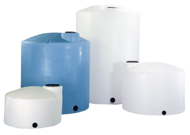
- Reference 5000 gallon tank for typical buried-service installation. Reference N-40164 5000 gallon Norwesco vertical as a typical large-volume tank where buried supply or distribution piping connects through one or more sidewall fittings, each requiring transition engineering.
The transition concentrates multiple stress mechanisms at a single point. The engineering response is to address each mechanism explicitly rather than to assume any one of them is negligible.
2. Heat-Fusion Joint Selection for Pipe-to-Pipe Sections
The buried HDPE pipe itself is jointed by heat fusion across its length. The fusion technique selection within the buried run sets the joint reliability that the pipe-to-tank transition will rely on:
- Butt-fusion as the primary jointing method. Butt fusion joints two pipe ends by heating both flat ends to the polymer melt temperature, then pressing them together until cooled. The resulting joint is monolithic with the parent pipe and matches the pipe's full pressure rating. Butt fusion is the dominant joint type for pipe sections from 2 inch to 65 inch diameter.
- Electrofusion for fittings and tight-quarters jointing. Electrofusion uses a fitting with embedded resistance wires that melt the fitting and pipe surfaces when energized. Electrofusion is used for fittings (tees, elbows, transition couplings) and for in-trench jointing where butt-fusion equipment will not fit. Electrofusion is slower than butt fusion but supports tight working clearances.
- Saddle-fusion for service connections. Saddle fusion joints a saddle-shaped fitting onto the pipe wall. The technique supports service-connection branches without cutting the main pipe. Saddle fusion is common in distribution piping and less common in industrial service piping.
- ASTM F2620 procedure compliance. All HDPE fusion joints follow ASTM F2620 procedure: surface preparation, heat-tool calibration, melt time, cool time, and joint pressure. Deviation from the procedure produces joints that may pass initial pressure test but fail in the buried service life.
- Operator certification and equipment calibration. Fusion crews are certified to PPI training standards. The heat tools are calibrated periodically. Joints performed by uncertified crews on uncalibrated equipment have field-failure rates an order of magnitude higher than joints performed by certified crews on calibrated equipment.
- Joint-test discipline. A representative joint from each work day is destructively tested (bend test, tensile test) to verify the joint quality. Joints that fail the destructive test invalidate the day's work and trigger investigation of equipment calibration or operator technique.
The fusion-joint discipline within the buried pipe section sets the baseline joint reliability. A buried run with disciplined fusion joints can match the parent pipe service life of 50 years or more; a buried run with shortcut fusion produces field failures within a few years.
3. Mechanical-Joint Transition for the Pipe-to-Tank Connection
The buried pipe terminates at the tank fitting through a mechanical-joint transition. The transition cannot be heat-fusion because the tank fitting is a different polymer assembly than the pipe. The mechanical-joint options:
- Flanged transition with HDPE stub end and metallic backing flange. The pipe terminates in a butt-fused HDPE stub end. The stub end has a flat sealing surface that mates against an ANSI 150 flat-faced flange. A metallic (typically galvanized steel or stainless steel) backing flange compresses the stub end against the tank flange. Bolts pass through both flanges to compress the joint. This is the dominant transition type.
- Mechanical-joint compression coupling. A compression coupling clamps onto the pipe outer diameter and onto a metallic spool that connects to the tank. The compression seal is supported by an EPDM or Buna gasket. The coupling supports installation in tight quarters and accommodates limited misalignment.
- Threaded-fitting transition for small bore. For pipes 1.5 inch and smaller, a threaded HDPE-to-NPT transition adapter may be used. The adapter screws into a tank bulkhead fitting and compresses against the pipe through a threaded ferrule. Small-bore transitions tolerate higher pressure but have less misalignment tolerance.
- Flanged tank-fitting versus bulkhead-tank-fitting selection. The tank-side mating surface is either a flanged fitting (larger bore, higher pressure rating) or a bulkhead fitting (smaller bore, gasketed thread connection). The selection depends on the bore size and the required pressure rating.
- Gasket material for the flange seal. EPDM gaskets handle most aqueous services. Viton handles aggressive chemicals. PTFE-envelope gaskets handle the most aggressive services at higher cost. The gasket selection follows the chemistry compatibility chart.
- Bolt selection and corrosion protection. Buried-service bolts are stainless steel (typically Type 316) for corrosion resistance. Galvanized steel bolts are acceptable for shallow-buried installations in benign soil but corrode in aggressive soil. The bolt selection is matched to the soil chemistry.
- Reference 1500 gallon tank for typical sidewall flange application. Reference N-40144 1500 gallon Norwesco vertical as a typical mid-size tank with a sidewall fitting that accepts a 2-inch or 3-inch flanged transition from buried HDPE supply piping.
The mechanical-joint selection trades the monolithic strength of fusion for the flexibility of separable connections. The transition is the maintenance-access point and the failure-replacement point; selecting a high-quality transition repays through field-service simplicity.
4. Thrust Restraint Engineering
The thrust force at the pipe-to-tank transition is generated by internal pressure acting on the pipe cross-section. Without restraint, the thrust drives the pipe away from the tank over time. The restraint engineering:
- Thrust force calculation. The thrust force equals the internal pressure times the pipe cross-sectional area. A 4-inch HDPE pipe at 50 psi internal pressure produces ~628 pounds of thrust (50 psi times 12.57 square inch cross section). A 6-inch HDPE pipe at 50 psi produces ~1,414 pounds. The values scale rapidly with pipe size and pressure.
- Thrust block as the primary restraint. A concrete thrust block is poured against undisturbed soil at the direction-change or termination point. The block transfers the thrust to the soil bearing capacity. Thrust block sizing follows AWWA C600 or equivalent and depends on soil bearing capacity, internal pressure, and pipe size.
- Restrained-joint-system as the alternative. Mechanical restraint hardware that binds adjacent pipe sections together against thrust is an alternative to thrust blocks. The restrained-joint system is appropriate where thrust block placement is impractical (high water table, congested utilities, restricted right-of-way).
- Tank-side restraint. The tank-side of the transition must also resist thrust. The tank fitting itself is integral to the tank wall (no bolt-loosening risk), but the connection between the buried pipe and the tank fitting transmits thrust to the tank. Tank-side support (a structural support brace, a pipe-clamp at the tank base) prevents the transmission to the tank wall.
- Thrust during pressure transients. Steady-state thrust is one consideration; pressure-transient thrust is another. Water hammer events drive pressure spikes far above steady-state, and the corresponding transient thrust can exceed the steady-state restraint capacity. Surge analysis is part of the restraint design for systems prone to water hammer.
- Thrust monitoring through movement detection. A thrust restraint that is failing (thrust block settling, restrained joint loosening) shows early signs through tank or pipe movement. Periodic survey-grade measurement of the tank position relative to fixed reference points detects movement before it produces leakage.
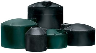
- Reference 2500 gallon cone-bottom for industrial applications. Reference N-40066 2500 gallon 30 degree cone bottom as a typical industrial tank where the discharge piping carries process flow under pressure and requires careful thrust analysis at the transition.
Thrust restraint is not optional. A buried piping system without thrust restraint will eventually separate at the transition; the only question is the timeline. Engineering the restraint at installation is much less expensive than discovering its absence after a separation event.
5. Settlement Accommodation Strategies
Differential settlement between the pipe trench and the tank pad is unavoidable to some degree. The accommodation strategies:
- Common foundation across pipe-end and tank pad. Where engineering and budget allow, the pipe-end portion of the trench is excavated to the same depth as the tank pad and supported on the same compacted base. The shared foundation produces shared settlement and minimizes differential stress.
- Flexible-coupling installation at the transition. A flexible coupling between the buried pipe and the tank fitting absorbs small relative motions (typically up to 1 inch axial and 5 degrees angular). Common flexible couplings include rubber-bellows and grooved-coupling designs. The coupling protects the rigid joint from settlement-induced stress.
- Pipe-flexibility loop near the transition. A short loop or offset in the buried pipe near the tank flexes to absorb settlement without transmitting stress. The flexibility-loop geometry is designed for the expected settlement range.
- Backfill compaction discipline at the trench-pad interface. The backfill at the trench-pad interface is compacted to the same density as the pad bedding. Inadequate compaction allows settlement that is much greater than the bulk trench settlement, producing concentrated bending stress.
- Long-term settlement monitoring. The installation survey records the initial position of the tank, the pipe-end, and the surrounding ground at fixed reference monuments. Periodic re-survey detects long-term settlement before it produces failure. The monitoring is particularly important during the first year after installation when most settlement occurs.
- Soil-improvement at sites with poor bearing. Sites with compressible soil (organic peat, soft clay) are improved through over-excavation, lime treatment, or geotextile reinforcement before installation. The improvement reduces the magnitude and rate of post-installation settlement.
Settlement is the slow stress mechanism at the transition. Sites that engineer for settlement and monitor against it sustain the joint integrity for the design life; sites that ignore settlement discover its consequences through eventual joint failure.
6. Buried-Service Inspection Regime
The buried-service joint cannot be visually inspected without excavation. The inspection regime substitutes other methods to assess joint health:
- Pressure-decay testing. The piping system is isolated and pressurized; the pressure is monitored over a defined hold time. Pressure decay above a threshold indicates a leak somewhere in the system. The test is non-invasive and detects leaks before they become surface symptoms.
- Acoustic leak detection. Listening devices placed at accessible points (tank top, valve box, hydrant) detect the high-frequency sound of pressurized leaks. Acoustic detection localizes the leak to a section of pipe; targeted excavation finishes the locate.
- Tracer-gas or dye injection. Helium tracer gas or fluorescent dye injected into the pipe surfaces at the leak location. The technique is sensitive to small leaks but requires the system to be drained and re-filled with the tracer.
- Surface-symptom monitoring. Visible signs of buried leaks (wet patches, vegetation darker green over the pipe, surface settlement, sinkholes) prompt investigation. The symptoms typically appear after the leak has been ongoing for some time.
- Periodic excavation inspection. Long service installations (10+ years) may benefit from periodic exposure of the buried joint for direct inspection. The exposure verifies that the gasket, bolts, and joint geometry remain in serviceable condition.
- Cathodic-protection monitoring (where metallic components are present). Galvanic-corrosion monitoring is performed on the metallic backing flanges and bolts where they are exposed to soil moisture. Corrosion-rate trending detects accelerated attack before structural failure.
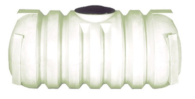
- Reference 1000 gallon cone-bottom for compact buried-service installations. Reference N-43852 1000 gallon 45 degree cone bottom as a typical compact installation where buried supply piping is short enough that pressure-decay testing reliably localizes leaks to the transition zone or the buried run.
The inspection regime substitutes systematic monitoring for the visibility that buried installation gives up. Sites that maintain the regime catch deteriorating joints early and replace them on schedule; sites that omit the regime discover failures through service interruption or environmental release.
7. Common Failure Modes at the Buried Transition
The buried pipe-to-tank transition fails in characteristic patterns that the design engineering should anticipate:
- Bolt-corrosion failure. Galvanized or carbon-steel bolts in aggressive soil corrode over years until the bolt cross-section is too thin to maintain joint compression. The joint loosens and leaks. Stainless-steel bolts in matching alloy nuts prevent the failure mode.
- Gasket-degradation failure. Gasket materials in incompatible chemical service degrade over years. The gasket may extrude (lose compression), embrittle (lose flexibility), or chemically dissolve (lose mass). Matching the gasket material to the chemistry prevents the mode.
- Stub-end-flatness failure. A heat-fused HDPE stub end that was machined out-of-flat at fabrication produces uneven gasket compression. The under-compressed portion leaks. Quality discipline at the fabrication stage prevents the mode.
- Settlement-bending failure. Differential settlement that exceeds the joint tolerance produces bending stress at the joint that cracks the HDPE stub end. Foundation engineering and flexible-coupling installation prevent the mode.
- Thrust-separation failure. Inadequate thrust restraint allows the pipe to slowly walk away from the tank. The joint separates. Thrust block or restrained-joint sizing prevents the mode.
- Frost-heave failure. Buried pipe in frost zones experiences soil heave when the surrounding soil freezes. The heave cycle bends the pipe near rigid restraints (such as the tank wall). Bury depth below frost line and granular bedding prevents the mode.
- Construction-damage failure. Future excavation near the buried pipe (utility installation, landscaping) damages the pipe or the joint. Marker tape, locator wire, and as-built drawings preserve the locate information for future work crews.
Each failure mode has a specific prevention pathway. Sites that engineer against each mode at installation and maintain the as-built records over service life rarely experience the failures; sites that under-engineer and fail to document discover the failures through service events.
8. Procurement Decisions That Affect Buried-Service Outcomes
The procurement decisions for the tank, the buried pipe, and the transition hardware set the long-term cost of the buried installation:
- Tank-fitting specification at the tank-procurement stage. The sidewall or bottom fitting that will accept the buried pipe is specified at tank order: bolt circle, gasket surface, drain configuration. Field-modification of tank fittings is feasible but compromises the tank pressure rating; specifying correctly at procurement is much preferred.
- Tank-foundation engineering coordinated with trench engineering. The site preparation for the tank pad is coordinated with the buried-pipe trench design so that settlement is shared rather than differential. Coordination at the design stage is much less expensive than retrofit.
- HDPE pipe pressure class selection. Buried HDPE pipe is specified to a pressure class (DR9 = 250 psi, DR11 = 200 psi, DR17 = 125 psi, DR21 = 100 psi). The class selection accommodates the operating pressure plus surge plus safety margin. Under-class pipe fails through fatigue; over-class pipe carries unnecessary capital cost.
- Stainless versus galvanized bolt specification. Stainless-steel bolts cost more at procurement but eliminate the corrosion-failure mode. The bolt-cost differential is a small fraction of the total transition cost; the failure-mode reduction is significant.
- Flexible-coupling inclusion in the bill of materials. Including a flexible coupling at the transition adds capital cost but absorbs settlement. The decision is made at design; later retrofit requires excavation and pipe modification.
- Concrete thrust-block specification or restrained-joint procurement. The thrust restraint is part of the installation scope. Selecting between concrete thrust block (lower material cost, more excavation) and restrained-joint hardware (higher material cost, less excavation) depends on site constraints.
- Marker tape and locator wire installation. Magnetic-detectable marker tape and locator wire are installed in the trench at standard depths. The investment is small at installation and pays through every future excavation work that can avoid the buried pipe.
- Reference 750 gallon cone-bottom for compact-footprint applications. Reference N-40811 750 gallon 20 degree cone bottom as a compact installation where buried supply piping handles process flow with shorter run length and lower thrust forces, allowing simpler restraint engineering.
The procurement decisions are coupled to the long-term failure rate of the buried installation. Decisions made at procurement that consider the buried-service failure modes produce installations that perform reliably for 30 to 50 years; decisions made on first-cost basis only produce installations with predictable mid-life failures.
9. The Buried Pipe to Tank Transition Engineering Conclusion
The buried HDPE pipe to polyethylene tank transition is the highest-stress interface in many industrial water and chemical systems. The engineering response is not to avoid the interface but to address each stress mechanism explicitly: heat-fusion discipline within the buried pipe section, mechanical-joint selection at the transition, thrust restraint engineering, settlement accommodation, buried-service inspection regime, and documented as-built records. The procurement decisions made at tank order, pipe order, and transition-hardware order set the long-term cost of the installation: tank-fitting specification, foundation engineering, pipe pressure class, bolt material, flexible-coupling inclusion, thrust-restraint approach, and locator-tape installation. Sites that engineer the buried transition across these dimensions sustain reliable service for the full design life of the installation; sites that shortcut the engineering produce predictable failures, environmental events, and customer service disruptions.
OneSource Plastics ships polyethylene tanks across the 5-brand catalog (Norwesco, Snyder, Chem-Tainer, Enduraplas, Bushman) with sidewall and bottom fitting configurations that accept buried HDPE supply or distribution piping transitions. Tank specification for any specific buried-service application is performed by the customer site engineer with reference to the operating pressure, the soil characteristics, the regulatory regime, and the coordinated foundation and trench engineering. List pricing on each product page; LTL freight to your ZIP via the freight estimator or by phone at 866-418-1777.
Recommended Tanks for This Guide
Live pricing, updated automatically · estimate freight to your ZIP.