Hurricane Tie-Down Design for Elevated Water Tanks in Coastal AHJ Zones (ASCE 7-22)
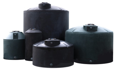
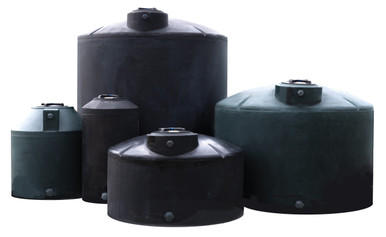
An empty 2,500-gallon polyethylene water tank weighs about 350 pounds. A 145 mph wind acting on the tank's projected area generates uplift and overturning forces that exceed that empty weight by an order of magnitude. Without engineered tie-down hardware, the tank does not stay where you put it. This guide walks the ASCE 7-22 wind-load engineering for above-ground water-storage tanks in coastal Authority Having Jurisdiction (AHJ) zones — risk category, basic wind speed, force coefficient, anchor sizing, and the failure modes that show up after the storm passes. Real OneSource catalog SKUs anchor the examples.
The governing document
ASCE/SEI 7-22, Minimum Design Loads and Associated Criteria for Buildings and Other Structures is the consensus standard adopted by reference into the International Building Code (IBC) and most state and local building codes. The 2022 edition updated coastal wind speeds — primarily on the coastal where recent hurricane experience drove conservative revisions — and refined provisions for tanks, silos, and bins (Chapter 30 and the Other Structures provisions in Chapter 29). Tank wind-load design references the 2022 wind-speed maps with adjustments for risk category, exposure, and topographic effects.
For state-specific hurricane planning context see Florida, Texas, Louisiana, North Carolina, and South Carolina.
Risk category — the first input
ASCE 7-22 Table 1.5-1 classifies structures by Risk Category based on consequence of failure. For water-storage tanks the typical mappings:
- Risk Category I — minor agricultural water storage where failure consequence is minimal. Lower mapped wind speed.
- Risk Category II — most rural-water and small-system reserves. The default for residential and light commercial water storage. Mapped wind speed Vult per the 2022 maps.
- Risk Category III — water storage serving critical facilities (hospitals, emergency services), or where tank failure could endanger people. Higher mapped wind speed.
- Risk Category IV — essential public-safety water reserves (fire suppression, hospital backup). Highest mapped wind speed.
The risk category drives the basic wind speed Vult that the design must withstand. For a typical rural residential 2,500-gallon water reserve tank in coastal Florida, Risk Category II applies, with Vult typically 150 mph in inland Broward County, 165 mph in eastern Miami-Dade, and up to 180 mph along the Florida Keys per the ASCE 7-22 maps.
Basic wind speed and design wind pressure
ASCE 7-22 Section 26.5 gives the basic wind speed Vult for Risk Category II at the project location, sourced from the wind-speed maps in Figure 26.5-1. The design wind pressure on a vertical cylindrical tank shell follows API 650 (which references ASCE 7) or the analogous force-coefficient method in ASCE 7 Chapter 29 for Other Structures:
P_WS = 18.6 * (V/120)^2 [lbf/ft^2 on the vertical projected area]
For a tank in a 150 mph design wind, P_WS = 18.6 * (150/120)^2 = 29.1 psf on the projected vertical area. For a 180 mph design wind, P_WS rises to 41.9 psf. These pressures act laterally on the projected silhouette of the tank.
Worked example — Norwesco 2,500-gallon vertical at Risk Category II, 150 mph
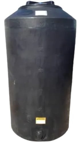
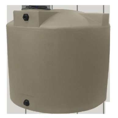
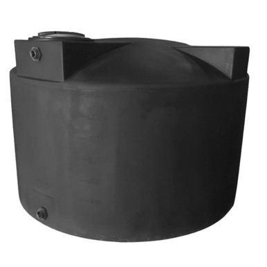
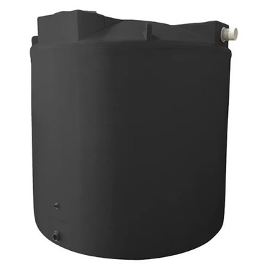
Real catalog SKU: Norwesco MPN 42040 (2,500 gallon vertical, 95" diameter x 91" tall, black HDPE, water duty, listed at $2,399.00). Projected vertical area:
A_proj = D * H = 95" * 91" = 8,645 sq in = 60.0 sq ft
Design wind pressure at Vult = 150 mph: P_WS = 29.1 psf. Lateral wind force on the tank:
F_lat = P_WS * A_proj = 29.1 * 60.0 = 1,746 lbf
Overturning moment about the base:
M_OT = F_lat * H/2 = 1,746 * (91/24) = 6,621 ft-lb
The empty tank weighs roughly 350 lbf; with an empty centroid at H/2 = 45.5 inches (3.79 feet) and a base radius of D/2 = 47.5 inches (3.96 feet), the resisting moment from self-weight is:
M_R = W * r = 350 * 3.96 = 1,386 ft-lb
Empty resisting moment is less than overturning moment by a factor of ~4.8. The empty tank tips over. Even when half-full (W ≈ 9,800 lbf for half capacity), the resisting moment grows enormously and the tank does not tip — but in hurricane conditions the worst-case design must assume the tank could be empty. Hence the tie-down requirement.
Anchor force per attachment
Specifying four equally-spaced lug straps, each carries roughly the lateral force divided by the number of resisting attachments:
F_anchor (per strap, lateral) = F_lat / N = 1,746 / 4 = 436 lbf
The uplift component (vertical) at the windward attachment is governed by the moment couple. Conservative design takes the worst-case anchor as carrying half the overturning moment divided by the lever arm:
F_uplift_max = M_OT / (D - 12")/12 = 6,621 / 6.92 = 957 lbf
Each engineered tie-down strap and anchor must be rated for the larger of the per-strap lateral force or the windward uplift force. In this example, ~960 lbf working load. Standard 1/2" epoxy-set wedge anchors in 4,000 psi concrete with 4" embedment carry working loads of roughly 1,200 to 1,800 lbf each in tension — adequate for this case with safety factor.
For a deeper read on anchor concrete connection see Tank Foundation Pad Engineering.
Force coefficient adjustments — H/D ratio
ASCE 7-22 specifies the force coefficient C_f for cylindrical structures based on H/D ratio. The 2,500-gallon Norwesco at 91/95 = 0.96 H/D is in the "short cylinder" range (0.25 ≤ H/D ≤ 4), where ASCE 7-16/22 explicitly addresses tank uplift loading on the roof in addition to the lateral wind load on the shell. For very tall, narrow tanks (H/D approaching 4) the force coefficient grows; for short squat tanks (H/D below 1) it is moderated.
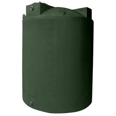
A taller, narrower tank — for example Norwesco's 2,000 gallon at 64" diameter x 153" tall (H/D = 2.39) — runs into a higher force coefficient and requires more conservative tie-down. A short squat tank like Norwesco MPN 42040 (H/D ≈ 1) is closer to the bottom of the force-coefficient curve.
Tank farm shielding — the overlooked correction
ASCE 7-22 includes provisions for tightly-spaced tank groups. When tanks are clustered in a farm with center-to-center spacing less than 1.25 D, the upwind tanks shield the downwind tanks but the wind force on individual tanks within the cluster can effectively double due to interference effects. The takeaway: tank farms in coastal zones must engineer to the doubled-pressure case, not the isolated-tank case. A common AHJ permit deficiency is treating each tank as isolated when in fact they are clustered.
For multi-tank farm design see Modular Tank Farm Design.
Strap hardware — what to specify
Engineered tie-down systems for polyethylene water storage tanks typically use:
- Polyester webbing straps rated for 4,000 to 8,000 lbf working load, with stainless steel ratchet buckles. UV-resistant polyester resists degradation outdoors.
- Stainless steel cable systems (3/16" to 5/16" diameter, 7x19 stranded) with marine-grade thimbles and turnbuckles, anchored to slab inserts.
- Rotomolded lug strap channels integrated into the tank dome at the factory — the Norwesco hurricane-rated lug feature on certain SKUs.
- Concrete anchors — 1/2" to 5/8" wedge anchors or epoxy-set rod, 4" minimum embedment in 4,000 psi concrete pad. ICC-ES evaluation report (ESR) compliance for the specific anchor brand and concrete strength.
The strap and the anchor are a system. Specifying a 6,000 lbf strap on a 1,200 lbf anchor leaves the system limited by the weakest link. Match the ratings.
For full water-tank category options browse Water Tanks.
The empty-tank failure mode
The most common hurricane tank failure is not structural shell rupture — it is uplift and lateral displacement of an empty or low-fill tank. Operators sometimes drain water tanks in advance of an approaching hurricane to "protect" them; this is exactly backwards. A full tank carries massive resisting moment from self-weight and is far more storm-resistant than an empty one. Operational guidance in coastal zones: fill the tank before the storm, not after. The water provides the ballast that keeps the tank on the slab.
The exception: tanks plumbed to active distribution systems may need to be drained for system isolation. In that case, the tie-down hardware must be sized for the empty-tank case, which is the design controlling case anyway.
Permit submittal — what AHJ wants to see
Coastal AHJ jurisdictions typically require a stamped engineering submittal for any water-storage tank above 500 gallons in a hurricane-prone region. The submittal package should include:
- Site location and ASCE 7-22 wind-speed map reference.
- Risk category determination per ASCE 7-22 Table 1.5-1.
- Tank specification — manufacturer, MPN, capacity, dimensions, weight empty/full.
- Wind-load calculation using the design wind pressure formula and projected area.
- Anchor force calculations per attachment, including the worst-case uplift.
- Anchor hardware specification — size, type, ICC-ES report number, embedment depth.
- Concrete pad specification — strength, thickness, reinforcement, edge distance to anchor.
- Strap or cable hardware specification with working load ratings.
- P.E. stamp from a licensed Professional Engineer in the jurisdiction.
For a state-specific permitting timeline see Tank Permitting Lead Time by State.
What goes wrong post-storm
Three recurring post-hurricane water-tank failures, ordered by frequency:
1. Tank sliding off slab
The most common failure mode: anchors held but the strap-to-anchor connection failed, allowing the tank to slide laterally off the slab. Often traced to undersized straps, corroded strap-to-anchor turnbuckles (carbon steel rather than stainless), or insufficient strap tension at install.
2. Empty tank uplift and tumble
Empty tanks lift off the slab during the storm, tumble downwind, and end up wedged in fences or trees. Almost always traced to either (a) an absence of tie-downs entirely, or (b) tie-downs sized for full-tank loading without considering the empty case.
3. Concrete spalling at anchor
Anchor pulled out of the concrete pad. Traced to insufficient anchor embedment, anchor too close to slab edge, or low-strength concrete (specified 3,000 psi where 4,000 psi was needed).
For a broader inventory of tank failure modes see Plastic Tank Failure Mode Analysis.
Topographic and exposure adjustments
The basic wind speed from the ASCE 7-22 map is a starting input, not a final answer. Two adjustments commonly apply for coastal water-tank installations:
- Exposure category per ASCE 7-22 Section 26.7. Most rural and small-town coastal installations are Exposure C (open terrain with scattered obstructions). Wide-open marsh, beach, or near-shore sites are Exposure D, which increases the velocity pressure. The exposure category is selected at the project location and applied through the K_z velocity pressure exposure coefficient.
- Topographic effect per ASCE 7-22 Section 26.8. Tanks installed on hilltops, ridges, or escarpments capture accelerated wind flow. The topographic factor K_zt multiplies the design pressure. For a tank near a coastal escarpment, K_zt of 1.3 to 1.6 is realistic; this can increase the design wind force by 30 to 60 percent.
A coastal Florida tank on a flat lot at Exposure C: K_z roughly 0.85-0.90 at tank height, K_zt = 1.0. Same tank on a coastal ridge: K_z still 0.85-0.90, K_zt up to 1.4. The same wind map speed translates to substantially different design pressures depending on the site.
The flood-zone overlap
Coastal hurricane planning rarely stops at wind. Storm surge and flood loading are governed by ASCE 24-22 (Flood-Resistant Design and Construction) and the FEMA Flood Insurance Rate Maps. A water tank in a Special Flood Hazard Area must address both the wind tie-down case and the buoyancy case — empty tanks float in inundated sites and can be carried inland by surge. The buoyancy resisting force is the empty tank weight; the buoyant uplift is the displaced water weight (8.34 lbf per gallon of submerged tank volume).
For a 2,500-gallon tank fully submerged in 4 feet of standing water, the buoyant uplift on the displaced submerged volume can readily exceed several thousand pounds — far more than the wind uplift case. Tie-down hardware in flood zones must be sized for the larger of the two cases. AHJ permit reviewers in flood zones will require both calculations.
Maintenance of the tie-down system
Tie-down hardware is not install-and-forget. Annual or biannual inspection should verify:
- Strap or cable integrity — UV degradation of webbing, corrosion of cable strands.
- Turnbuckle and ratchet condition — corrosion, paint failure, working order.
- Anchor seating — visible movement, hairline cracking around the anchor base, surface spalling.
- Strap tension — webbing typically loosens over time; re-tension to install spec.
For inspection cadence guidance see Tank Inspection SOP.
Bottom line
ASCE 7-22 wind-load engineering for above-ground polyethylene water tanks in coastal AHJ zones is straightforward arithmetic once the inputs are pinned: risk category from Table 1.5-1, basic wind speed from the regional map, design pressure from the 18.6 (V/120)^2 formula, projected area from tank dimensions, anchor force from the simple lateral and overturning calculations. The empty-tank case usually controls. Tie-down hardware must be a matched system — strap, anchor, slab — with each component rated for the worst-case load. Permit submittals require a P.E. stamp and full calculation package in most coastal jurisdictions. Fill the tank before the storm, not after.
For full water tank inventory browse Water Tanks. For the related vertical wind-load engineering pillar see Vertical Tank Wind Load Engineering. For state-by-state coastal regulation context see State Tank Regulations.
Recommended Tanks for This Guide
Live pricing, updated automatically · estimate freight to your ZIP.