Tank Piping Support Engineering for Polyethylene and Steel Pipe Runs Off Plastic Bulk Tanks: Thermal Expansion Math, Support Interval Tables by Material and Schedule, and Anchor-Point Selection That Does Not Transmit Stress Into the Tank Shell


Piping support is the most under-engineered element of a typical tank installation. The tank itself gets specification review, foundation calculation, and anchor design. The piping that runs from the tank to the process equipment too often gets installed with whatever clamps and brackets are on the truck, with support intervals determined by what looked reasonable at the time, and with anchors that transmit thermal expansion stress directly into the polyethylene tank shell. This combination is the root cause of cracked outlet bulkheads, fitting leaks that worsen seasonally, and pipe sag that progresses to bowed runs over a decade of service.
This article walks the engineering. The references are ASME B31.3 (process piping), MSS SP-58 (pipe hangers and supports), MSS SP-69 (selection and application of pipe hangers), the Plastics Pipe Institute (PPI) TR-21 thermal-expansion methodology, the manufacturer technical bulletins from Norwesco, Snyder, Chem-Tainer, Enduraplas, and Bushman on bulkhead-fitting load limits, and ASTM D2447 for HDPE pipe dimensions. The objective is the field-installable support design that survives 25 years of thermal cycling without transmitting stress into the tank.
1. Why Tank-Outlet Piping Stress Matters More Than People Think
Polyethylene tank bulkhead fittings are designed for the static loads of liquid through the fitting and the modest dynamic loads of normal flow. They are not designed to absorb the thermal-expansion stress of an unsupported pipe run, the cantilevered weight of valves and instrumentation hung off the fitting, or the bending moment imposed when a clamped pipe expands and the tank is the only fixed point in the system. Bulkhead fittings that fail in service usually fail not because the fitting was defective but because the piping was attempting to use the fitting as an anchor.
The consequence: cracked thread bosses, oval-shaped bulkhead seats that no longer seal against the gasket, and in extreme cases full bulkhead pull-out where the fitting tears free of the tank wall. The leak is sudden, often catastrophic, and the operator's first reaction is to blame the fitting. The actual cause is a piping support failure several feet downstream.
The engineering remedy is straightforward but it requires deliberate design: anchor the piping to structure, not to the tank. Allow thermal expansion in the run between the anchor and the tank. Size and space supports per the material and schedule of the pipe. Treat the bulkhead as a flexible terminator, not as a structural member.
2. Thermal Expansion Math by Pipe Material
The first calculation in any tank-outlet piping design is thermal expansion. The pipe will grow when warm and contract when cool, and the design must accommodate the movement without transmitting axial stress to the tank. The coefficients of linear thermal expansion (inch per inch per degree Fahrenheit) for common piping materials:
- HDPE pipe: 0.00009 in/in/F. The largest of the common piping materials. A 50-foot run from a tank to a pump skid expanding through a 60 F temperature swing grows 0.32 inch — material-significant movement that must go somewhere.
- PVC pipe: 0.000030 in/in/F. About one-third of HDPE. Same 50-foot run, 60 F swing: 0.11 inch growth.
- CPVC pipe: 0.000034 in/in/F. Slightly higher than PVC. Common in hot-water and process service.
- Stainless steel pipe (304/316): 0.0000099 in/in/F. About one-ninth of HDPE. Same 50-foot run, 60 F swing: 0.036 inch.
- Carbon steel pipe: 0.0000063 in/in/F. The lowest of common materials. Same 50-foot run, 60 F swing: 0.023 inch.
- Polypropylene pipe: 0.000083 in/in/F. Comparable to HDPE.
- PVDF pipe: 0.000079 in/in/F. Comparable to HDPE.
The temperature swing matters more than installers usually appreciate. An outdoor pipe run in a temperate climate sees an annual swing of roughly 80 F (winter low to summer high) and a daily swing of 30-40 F in shoulder seasons. A pipe run in a sun-exposed location adds another 20-30 F to the maximum temperature. The design temperature swing for an outdoor run is typically taken as 100-120 F to capture the realistic operating envelope.
The expansion calculation is then: change in length equals coefficient times original length times temperature change. A 100-foot HDPE run through a 100 F swing grows 0.108 inches per foot — about 10.8 inches over the full run. That is the displacement that must be accommodated by expansion loops, flexible connectors, or compliant supports. It is not optional. An HDPE run that is rigidly clamped at both ends through that thermal range will either buckle, crack, or pull a fitting out of the tank.
3. Pipe Support Interval Tables by Material and Schedule
The next calculation is support spacing. Pipe sags between supports under its own weight plus the weight of the contained fluid. Excessive sag distorts the run, creates low points where condensate or vapor collects, and stresses the tank-end fitting if the tank-side support is too distant. MSS SP-69 provides recommended maximum support intervals by material and pipe size; the values below are conservative ranges from PPI TR-21 and steel-piping handbook references for water-filled service:
- HDPE pipe, 1-inch nominal: 4-foot maximum interval. HDPE is the most flexible of common pipe materials and requires close support to maintain the design slope.
- HDPE pipe, 2-inch nominal: 5-foot interval.
- HDPE pipe, 4-inch nominal: 6.5-foot interval.
- HDPE pipe, 6-inch nominal: 8-foot interval.
- PVC Schedule 40, 1-inch: 5-foot interval.
- PVC Schedule 40, 2-inch: 7-foot interval.
- PVC Schedule 40, 4-inch: 9-foot interval.
- PVC Schedule 80, 4-inch: 11-foot interval. The thicker wall increases stiffness.
- CPVC Schedule 80, 2-inch: 6-foot interval at 73 F. Reduce to 4-foot at 180 F operating temperature; CPVC support spacing is highly temperature-dependent.
- Carbon steel Schedule 40, 2-inch: 13-foot interval. Steel's stiffness dominates; supports can be spread.
- Carbon steel Schedule 40, 4-inch: 17-foot interval.
- Stainless steel, 2-inch: 12-foot interval. Marginally less stiff than carbon steel due to lower modulus.
The support spacing changes with operating temperature for thermoplastic materials. HDPE at 140 F has roughly half the stiffness of HDPE at 73 F; the support interval should be reduced 30-40 percent for high-temperature service. The PVC values above are for ambient water service; PVC near its 140 F upper limit needs supports at roughly two-thirds the ambient interval.
The supports must also accommodate the thermal-expansion movement calculated in the previous section. A rigid clamp at every support point prevents axial movement and buckles the pipe. The standard solution: alternating fixed and rolling supports. Fixed supports at endpoints and at major equipment connections (pump suction, valve manifolds); rolling, sliding, or U-bolt supports between fixed points to allow axial expansion while maintaining vertical support. The fixed-to-rolling ratio depends on the run length and expansion magnitude.
4. The Anchor-Point Engineering — Where the Fixed Supports Belong
The fixed supports define the thermal-expansion behavior of the run. Between two fixed points, the pipe will grow into the rolling supports, push against any obstruction, and impose axial force on the fixed points. The engineering principle: place fixed supports where structural anchorage is available, NOT at the tank bulkhead.
The standard fixed-support locations for tank-outlet piping:
- At the tank-side, on independent structure within 2-3 feet of the bulkhead. A short pipe stub from the bulkhead, then a flexible expansion joint or a length of compliant hose, then a fixed support on a steel stand or wall bracket that is anchored to the foundation, NOT to the tank. The flexible element absorbs all thermal movement upstream of the fixed support; the bulkhead sees only the static fluid load.
- At the equipment-side, on the equipment skid or its anchor point. The pump skid, valve manifold, or process equipment provides the second fixed point.
- At intermediate locations only when the run is long enough to require expansion-loop accommodation. A run between two fixed points longer than roughly 80-100 feet (HDPE) needs an expansion loop or sliding-joint between the two fixed points.
The flexible expansion element near the tank is the single most important detail in the entire installation. Acceptable forms include a stainless-steel-braided flexible hose rated for the operating chemistry, a rubber expansion joint with control rods, a Z-loop or U-loop in the pipe run itself, or a bellows expansion joint. The element must absorb the calculated thermal-expansion movement plus a 25-50 percent safety margin, and it must be installed with adequate clearance to deflect freely without binding.
5. Bulkhead Fitting Load Limits and How to Stay Below Them
The polyethylene tank bulkhead fitting has published load limits from the tank manufacturer that are typically expressed as static fluid load and a small allowance for hose or pipe weight. Norwesco, Snyder, Chem-Tainer, Enduraplas, and Bushman each publish guidance and the values vary by tank wall thickness and fitting type, but the common patterns:
- Bulkhead fittings 2-inch and smaller: typically rated for 50-100 pounds of cantilevered weight including any attached valve. Heavier valves must be independently supported.
- Bulkhead fittings 3-inch through 6-inch: typically 100-300 pounds of cantilevered weight. A flanged 4-inch ball valve weighing 35 pounds is within the envelope; a flanged 6-inch knife-gate valve weighing 90 pounds plus 30 feet of unsupported pipe full of water (significant additional weight) is well beyond.
- Axial pull-out from thermal expansion: bulkhead fittings are NOT rated for sustained axial tension or compression. Any axial loading from thermal expansion must be intercepted by the support system before it reaches the bulkhead.
- Bending moment from cantilevered piping: the bulkhead is rated for nearly zero bending moment. A horizontal pipe stub more than about 18 inches long, with a valve hung at the end, is approaching the bending-moment limit even with no flow.
The design rule that satisfies all of these constraints: every bulkhead fitting on a polyethylene tank must have an independent pipe support within 18-24 inches of the fitting. The support carries the weight and absorbs any thermal or vibrational loads. The bulkhead carries only the static fluid pressure.
6. Vertical Pipe Support — The Riser From a Tank Outlet
Many tank installations have a vertical pipe rising from a bottom outlet to a horizontal manifold above. The vertical run has its own support requirements that differ from horizontal:
- Riser support immediately above the tank-outlet bulkhead. A clamp anchored to a structural stand intercepts the pipe weight before it reaches the bulkhead. The clamp may be a simple U-bolt for steel pipe or a saddle clamp for HDPE/PVC.
- Intermediate riser supports per the horizontal-spacing table, halved. A vertical pipe run is more sensitive to lateral movement (wind, vibration, accidental impact) than a horizontal run. The MSS SP-69 recommendation is to halve the maximum horizontal interval for vertical runs.
- Top-of-riser anchor where the riser turns horizontal. The elbow at the top is a structural transition and must be supported; otherwise the entire riser weight hangs off the bottom anchor and creates a cantilever moment that the tank-side support cannot absorb.
- Thermal-expansion accommodation via offset legs or expansion joints. A vertical run that is rigidly clamped both top and bottom will buckle laterally as it tries to expand. The most common solution is a small offset (a 90-degree offset of 12-18 inches) at the top of the riser that absorbs vertical thermal movement.
The riser also carries hydraulic shock loads from valve closures and pump start/stop transients. Water hammer in a closed pipe run can briefly multiply the static-pressure stress by 5-10x. Riser supports must be rated for these dynamic loads, which usually means a structural stand rather than a wall-mounted bracket.
7. Outdoor Installations — UV, Corrosion, and Wind-Load Considerations
Outdoor pipe runs from tanks add three engineering factors beyond the indoor case:
- UV degradation of the pipe and supports. Standard PVC and HDPE pipe in continuous UV exposure degrades over 10-20 years; the carbon-black or pigmented variants extend this materially. Pipe supports must use UV-stable plastic clamps, hot-dip galvanized steel, or 304/316 stainless. Plain electrogalvanized supports rust through in 3-5 years of outdoor service.
- Wind-load contribution to support sizing. ASCE 7 wind-pressure coefficients applied to the projected pipe area give the lateral wind load that supports must absorb. A 6-inch pipe in a 110 mph design-wind region sees roughly 30 pounds per linear foot of lateral wind load; the supports and their anchors must transmit this to the structure.
- Solar-gain temperature elevation. A black-pigmented outdoor pipe in direct sun can reach 140-150 F internal temperature on a summer afternoon even when ambient is 95 F. The pipe-material temperature rating, the support-spacing temperature derate, and the thermal-expansion calculation must all use the worst-case operating temperature, not the ambient.
The support hardware specification for outdoor installations: 304 stainless or hot-dip galvanized steel for clamps and brackets, UV-resistant elastomer for any rubber components, and stainless-steel anchor bolts into concrete with epoxy-set capsules to avoid corrosion at the foundation interface.
8. Tank Selection and Outlet Configuration That Simplifies Piping Design
The piping engineer's job is materially easier when the tank is specified for the application:
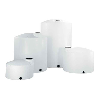
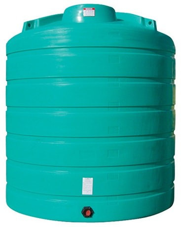
- Vertical bulk tanks with bottom-outlet bulkhead in a fitting-friendly orientation. Reference N-40164 5,000 gallon Norwesco vertical and N-43128 10,000 gallon Norwesco vertical, both XLPE construction with bulkhead fittings positioned for clean horizontal pipe runs and standard outlet sizes.
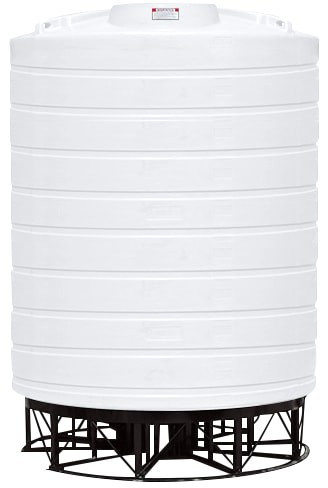
- Cone-bottom tanks for full-drainage process service. Reference N-43852 1,000 gallon 45-degree cone; the cone outlet at the bottom apex naturally orients the piping vertically downward, simplifying support layout for the riser-to-manifold geometry.
- Double-wall containment tanks for hazardous-chemistry service. Reference Snyder Captor double-wall units which include integrated containment and engineered bulkhead-fitting locations that account for piping strain isolation. Models like the SII-1006600N42 10,000 gallon XLPE Captor are sized for industrial chemistry runs with the engineering documentation that piping support design requires.
The tank selection should also account for the operating chemistry's specific gravity, the planned outlet sizes, and the freeboard required for thermal expansion of the tank contents (a separate calculation from pipe expansion but usually relevant in the same design package).
9. The Inspection and Maintenance Cadence for Pipe Support Systems
Pipe supports degrade slowly. The visible signs of support failure are usually subtle until they become catastrophic. Recommended inspection cadence:
- Annual visual inspection. Walk every pipe run from tank to terminus. Document support locations, fastener condition, sag at midspan, alignment of clamps, and corrosion at metal components. Photograph anything questionable for trend analysis.
- Five-year detailed inspection. Measure pipe sag at maximum-span locations and compare to the original installation baseline. Verify thermal-expansion elements are still articulated and not bound or rusted in place. Confirm all anchor-bolt torques on critical fixed supports.
- After any major thermal event. A freeze that cracks the heat tracing, a fire near the run, or an extreme heat wave can drive the run beyond design temperature. Re-inspect the run after any out-of-envelope thermal exposure.
- After any seismic or wind event near the design envelope. Pipe-support anchorage is loaded dynamically during such events; check the fasteners and anchor bolts.
The maintenance philosophy: catch the small problems (corroded support, loose anchor bolt, slight sag at midspan) before they become large problems (pipe rupture, bulkhead pull-out, tank-side flooding). The cost of a thorough annual walk-through is trivial relative to the cost of an unplanned tank outage.
10. The Engineering Discipline Conclusion
Tank piping support is not a parts-list problem. It is a design problem with calculations, material specifications, and inspection requirements. The installer who clamps a long HDPE run rigidly to a wall every 12 feet and runs the line straight into a bulkhead has set up a fitting failure that will appear within 3-5 thermal cycles. The installer who calculates the thermal expansion, sets fixed and rolling supports per MSS SP-69 spacing, places a flexible element near the bulkhead, and anchors all fixed supports to structure independent of the tank has built a system that survives 25 years.
OneSource Plastics ships the polyethylene tank that is the upstream end of these piping designs across all 5 brands — Norwesco, Snyder, Chem-Tainer, Enduraplas, Bushman — with bulkhead-fitting specifications, dimensional drawings, and load-rating documentation that the piping designer needs. List pricing by SKU is on the product page; LTL freight to your ZIP is quoted separately via the freight estimator or by phone at 866-418-1777. For related installation engineering see tank plumbing system design walkthrough and tank foundation engineering.
Recommended Tanks for This Guide
Live pricing, updated automatically · estimate freight to your ZIP.