Centrifugal Pump Tank-Bottom Suction vs Side-Mount Suction: Cavitation Tradeoffs, Submergence Calculations, Vortex-Suppression Geometry, and the Suction Architecture That Pumps the Tank Empty Without Damaging the Impeller


The centrifugal transfer pump connected to a polyethylene bulk tank has two basic suction configurations: bottom-outlet suction, where the pump draws from a fitting at or near the tank floor, and side-mount suction, where the pump draws from a fitting in the cylindrical wall above the floor. Both configurations work; both have failure modes; and the engineering decision between them affects pump life, NPSH margin, residual heel volume, and the cavitation behavior at the end of the drain cycle. The wrong choice for the application produces a pump that runs for six months and then needs an impeller replacement, or a tank that leaves 200 gallons of unrecoverable heel every time it drains.
This article walks the engineering of suction architecture for centrifugal pump installations on polyethylene bulk tanks across the five-brand catalog (Norwesco, Snyder, Chem-Tainer, Enduraplas, Bushman). The references are the Hydraulic Institute Standard ANSI/HI 9.6.6 (rotodynamic pump piping standards), the pump manufacturer technical bulletins from Goulds, Gorman-Rupp, March Manufacturing, Price Pump, and Finish Thompson, and field forensic data from chemical-transfer and water-supply installations where suction sizing required revision. The objective is the suction configuration that delivers consistent NPSH margin across the full drain cycle, suppresses vortex formation at low liquid levels, and pumps the tank as close to empty as the application can tolerate.
1. The Suction Architecture Decision Has Four Variables
The suction architecture decision is not just bottom vs side. It involves four interacting variables that have to be specified together:
- Suction location on the tank: bottom-center outlet (for cone-bottom tanks), bottom-side outlet (for flat-bottom tanks with side-fitted bulkhead), wall-mount outlet at low elevation (typically 4-6 inches above tank floor), wall-mount outlet at mid-elevation (above the trash and settled-solids zone).
- Pump elevation relative to the tank: flooded suction (pump centerline below tank low liquid level — most common configuration), suction lift (pump centerline above tank low liquid level — limited to specific small-pump applications and never optimal), self-priming pump with above-tank elevation.
- Suction piping geometry: straight run from tank to pump suction with no abrupt direction changes, or compromised geometry with elbows and reducers in the suction run.
- Foot valve, strainer, and filter selection: pump-mounted basket strainer, in-line Y-strainer, foot valve at the tank outlet, no straining (relies on tank inlet filtering).
Each combination of these four variables has a different NPSH-available calculation, different vortex-formation tendency, different residual heel volume at end of drain, and different operations-and-maintenance burden. The engineering work is to select the combination that fits the application — not to default to whatever the contractor proposes on the first quote.
2. Bottom-Outlet Suction: When It Is the Right Choice
The bottom-outlet suction configuration takes the suction line from a fitting at or near the tank floor — typically the cone tip on a cone-bottom tank, or a low-side bulkhead fitting on a flat-bottom tank. The advantages:
- Maximum drain depth. Bottom suction takes the residual liquid down to the level where vortex breakdown occurs (typically a few inches above the outlet); side suction leaves a heel equal to the elevation of the side fitting plus the vortex margin.
- Simplest piping geometry. A direct vertical run from the bottom outlet to the pump suction provides the cleanest hydraulic path with minimal pressure loss and no air-pocket formation in the suction line.
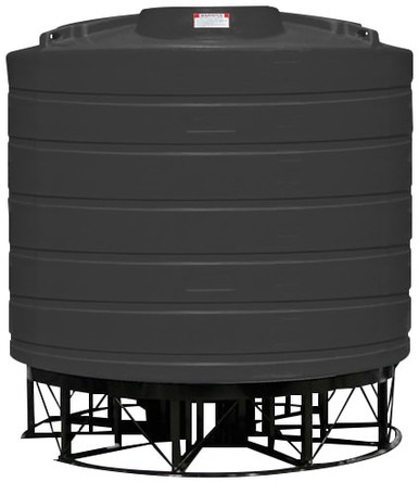
- Compatibility with cone-bottom tanks. Cone-bottom tanks are designed for full-drain operation with bottom suction; the cone geometry funnels material to the outlet, and the bottom-outlet pump configuration realizes the design intent.
The disadvantages:
- Settled-solids ingestion. Slurries and chemicals with suspended solids settle to the bottom during static hold; bottom suction draws the settled material into the pump on first start-up, causing impeller wear and potential plugging. Mitigated by a coarse strainer at the suction or by routine recirculation to keep solids in suspension.
- Tank-bottom mechanical loading. The bottom-outlet fitting and the suction piping below the tank apply mechanical load to the tank floor that the polyethylene shell was not designed to carry. The remedy is engineered support of the suction piping that does not transmit stress into the tank fitting.
- Drain accessibility for tank cleaning. A bottom-outlet configuration with permanently attached suction piping complicates tank cleaning and inspection; the piping has to be disconnected for any internal access. Mitigated by a quick-disconnect fitting at the outlet or by side-access cleaning ports.
Bottom-outlet suction is the right choice for cone-bottom tanks, for clear-fluid applications where settled solids are not a concern, and for installations where maximum drain depth is the operational priority. Reference N-43848 300 gallon 45-degree cone and N-40289 500 gallon 30-degree cone for the canonical cone-bottom configurations where bottom suction is the correct architecture.
3. Side-Mount Suction: When It Is the Right Choice
The side-mount suction configuration takes the suction line from a wall-mount bulkhead fitting at low to mid elevation on the cylindrical tank wall — typically 4-6 inches above the floor for low-side fittings, 12-24 inches above the floor for mid-side fittings. The advantages:
- Bypass of settled solids. A side fitting at 4-6 inches above the floor draws clean liquid from above the settled-solids zone, leaving the heel of accumulated solids in place. The settled material is removed during scheduled cleaning rather than dragged through the pump.
- No mechanical loading on the tank floor. The side fitting and the suction piping are supported by the tank wall and external piping supports rather than by the floor; no concentrated load on the polyethylene bottom.
- Cleaning and inspection access. The bottom of the tank remains accessible for sweep cleaning, inspection, and emergency drain via a separate floor outlet that is independent of the operating suction.
- Vortex margin. A side suction at low to mid elevation has more submergence margin at the suction point than a bottom suction has, particularly during the late-cycle low-level operation; vortex breakdown occurs at lower absolute liquid level.
The disadvantages:
- Residual heel volume. A side suction at 4-6 inches above the floor leaves a 4-6 inch residual heel that is not pumpable through the operating suction. For a 5000-gallon vertical tank with a 96-inch diameter, a 4-inch heel is roughly 125 gallons of unrecovered volume per drain cycle. Acceptable for most applications, expensive for high-value products.
- Suction piping geometry. Side suction requires a horizontal or near-horizontal run from the tank to the pump, with at least one elbow before the pump suction. The added piping length and the elbow increase the suction-side pressure loss and reduce the NPSH-available margin.
- Air-pocket potential. Horizontal suction runs accumulate air at high points; the suction piping must be sized and routed to allow continuous gas-trap-free flow, or fitted with vent points that the operator clears at startup.
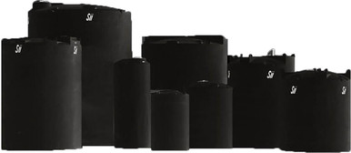
Side-mount suction is the right choice for flat-bottom vertical tanks, for slurry and suspended-solid applications where bottom-zone bypass matters, and for installations where tank cleaning access trumps last-gallon recovery. Reference N-40164 5000 gallon vertical and N-43128 10,000 gallon vertical for the canonical flat-bottom configurations where side suction is typically the correct architecture.
4. NPSH-Available Calculation Across the Drain Cycle
The NPSH-available at the pump suction is the critical performance parameter that determines whether the pump runs cleanly or cavitates. The calculation is:
NPSHa = Hatm + Hstatic - Hvap - Hfriction
Where Hatm is the atmospheric pressure converted to head of the pumped liquid (typically 33-34 feet for water at sea level, less at elevation), Hstatic is the static head from the liquid surface in the tank to the pump suction (positive for flooded suction, negative for suction lift), Hvap is the vapor pressure of the pumped liquid at operating temperature converted to head (typically 0.6-1 foot for water at 60-80 F, much higher for volatile chemicals), and Hfriction is the friction loss in the suction piping at the design flow rate.
- Flooded suction with bottom outlet on a cone-bottom tank: Hstatic = (full liquid level above pump centerline) at the start of the drain cycle, falling toward zero (or going negative if the pump is above the cone tip) at the end of the drain. NPSHa is favorable at start, marginal at end.
- Flooded suction with side outlet at low elevation: Hstatic = (liquid level above the pump centerline) with the pump centerline below the side outlet elevation. Hstatic falls to zero when liquid level reaches the side outlet elevation; below that, the pump runs out of suction head.
- Self-priming pump with elevated centerline: Hstatic is negative throughout the drain cycle. The pump must create vacuum to lift the liquid. NPSHa is constrained by atmospheric pressure minus vapor pressure minus piping losses minus suction lift; rarely exceeds 15-20 feet of effective suction lift in practice.
The NPSH-required (NPSHr) for the pump is published on the pump curve as a function of flow rate. The design rule is NPSHa minus NPSHr must be at least 3 feet (the Hydraulic Institute recommended margin); some chemical and slurry pumps require 5-10 feet of margin to avoid cavitation across the full operating range.
5. Vortex Formation at Low Liquid Level
As the liquid level in the tank falls toward the suction outlet, the radial flow pattern at the outlet develops increasing rotational momentum. At sufficiently low liquid level, the rotation forms a visible vortex with an air-core extending from the liquid surface down to the suction inlet. Once the air-core reaches the suction, the pump ingests air and either loses prime, cavitates severely, or surges between flowing and starved operation.
The vortex-formation submergence (the minimum liquid depth above the suction at which the air-core breakthrough occurs) depends on the suction velocity, the tank geometry, the suction-line geometry, and the proximity of the suction to tank walls or other features. The Hydraulic Institute Standard 9.8 provides curves for minimum submergence vs Froude number (a non-dimensional parameter combining suction velocity, gravity, and characteristic length). For typical industrial pump suctions, the minimum submergence to avoid vortex breakthrough is in the range of:
- 3-6 inches for low-velocity suction (under 2 ft/sec) at the suction inlet.
- 6-12 inches for moderate-velocity suction (2-4 ft/sec).
- 12-24 inches or more for high-velocity suction (4+ ft/sec) typical of high-flow pump applications.
The vortex margin must be added on top of the static-head requirement. For a side-mount outlet at 6 inches above the floor with a moderate-velocity suction requiring 8 inches of vortex submergence, the practical drain limit is 14 inches above the floor — leaving roughly 14 inches of heel that cannot be pumped without vortex breakthrough.
6. Vortex-Suppression Hardware
The vortex-margin requirement can be reduced by hardware that disrupts the rotational flow pattern at the suction. Three common approaches:
- Vortex-breaker plate at the suction inlet. A flat plate or cross-vane structure mounted directly above the suction inlet that disrupts the rotational flow before it can develop into a coherent vortex. Reduces the vortex-margin requirement by 30-50 percent at the cost of slightly higher friction loss.
- Suction-can or sump configuration. A separate small reservoir below the main tank with the actual pump suction taking from the bottom of the sump. The sump is sized to hold roughly the vortex-margin volume, and the main tank drains through a controlled overflow into the sump. The pump sees stable suction conditions in the sump regardless of main-tank level.
- Anti-rotation baffles in the tank. Vertical baffles attached to the tank wall or floor that prevent the bulk liquid from developing rotation as the level falls. Most effective in tanks with a single eccentric outlet; less effective in tanks with central outlets.
The suppression hardware decision depends on the residual-heel sensitivity of the application. For a chemical tank where every gallon matters, vortex breakers and sump configurations pay off. For a water tank where 50 gallons of heel is operationally trivial, the standard suction without vortex hardware is acceptable.
7. Pump Mounting Elevation and the Self-Priming Question
The flooded-suction configuration (pump centerline below the tank low liquid level) is the default for chemical-transfer and water-supply installations because it eliminates the priming question and provides the most NPSH-available margin. The pump is positioned at grade or below grade, with the suction line rising vertically from the pump to the tank outlet.
The self-priming configuration (pump centerline above the tank low liquid level) is used when the pump location must be at grade and the tank is partially below grade, or when the operator needs the flexibility to drain multiple tanks from a portable pump connection. Self-priming pumps have a built-in air-handling chamber that holds a priming charge and develops the initial vacuum to draw liquid up the suction line. The trade-offs:
- Suction lift limit: theoretical maximum 33-34 feet at sea level, practical maximum 15-25 feet depending on liquid temperature, vapor pressure, and piping friction. Higher elevations and warmer fluids reduce the achievable lift.
- Priming time: 30-90 seconds typical for a properly sized self-priming pump; longer for compromised piping or excessive lift.
- NPSH penalty: the suction-lift configuration consumes a large fraction of the available NPSH on the static lift, leaving less margin for friction loss and vapor-pressure variation.
The self-priming configuration is the right choice when operational flexibility (portable pump, multiple tank connections, above-grade installation) outweighs the NPSH penalty. The flooded-suction configuration is the right choice when the application is a fixed installation with predictable operation and the pump can be located below the tank.
8. Strainer and Filter Strategy
The pump suction must be protected from particulate ingestion that damages the impeller, plugs the volute, or compromises the mechanical seal. Three filter-protection strategies:
- Tank-side coarse strainer: a basket strainer or screen at the tank outlet, sized for the maximum particle the pump can pass cleanly. Removes the large debris that would otherwise jam the impeller.
- Pump-side basket strainer: a Y-strainer or basket strainer immediately upstream of the pump suction, accessible for cleaning without disconnecting the tank piping. The standard configuration for most chemical and water transfer installations.
- Foot valve at the tank outlet: a check valve at the tank outlet that prevents back-flow when the pump stops. Maintains the prime in the suction line. Required for self-priming pump installations with significant suction lift; optional for flooded-suction installations.
The strainer-cleaning cadence is part of the operations plan. A 100-mesh basket strainer on a chemical service may need cleaning weekly; a 40-mesh strainer on clean water service may go months between cleanings. The strainer differential-pressure gauge, monitored against a baseline trend, indicates when cleaning is due.
9. Tank Selection and Suction Architecture Together
The suction architecture decision is materially easier when the tank is specified with the pump installation in mind from the start. The engineering brief should include the pump selection, the suction line geometry, the residual-heel target, and the NPSH margin so the tank model and the suction package can be selected together.
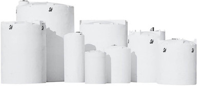
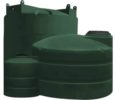
- Cone-bottom tanks for bottom-suction applications: reference N-43845 160 gallon 45-degree, N-43848 300 gallon 45-degree, and N-40289 500 gallon 30-degree. The cone geometry and the bottom outlet are designed for full-drain operation with flooded-suction pump architecture.
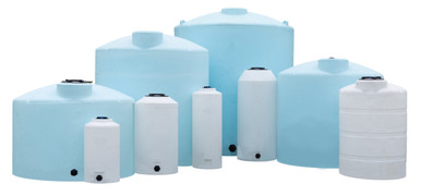
- Vertical bulk tanks for side-suction applications: reference N-40164 5000 gallon and N-43128 10,000 gallon, both XLPE construction with multiple wall-mount fitting options that the contractor can specify at any reasonable elevation for the application.
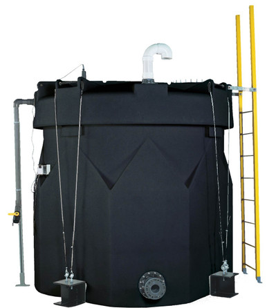
- Snyder Industries Captor double-wall: reference SII-1006600N42 10,000 gallon. The double-wall construction provides additional fitting placement flexibility and the secondary containment that some chemical-transfer installations require.
The procurement conversation should include the suction architecture as a specified scope, with the pump model, the suction-line geometry, and the residual-heel acceptance documented before the tank ships. List pricing on the BC product page is the starting point; LTL freight to your ZIP and the pump-and-piping installation are quoted separately. Reference the freight estimator or call 866-418-1777 to coordinate the packaged scope.
10. The Suction Engineering Conclusion
The suction architecture decision is not a default. Bottom-outlet suction maximizes drain depth and is the natural choice for cone-bottom tanks; side-mount suction bypasses settled solids and is the natural choice for flat-bottom slurry service. Either choice has consequences for residual heel, NPSH margin, vortex behavior, and pump life that should be engineered before the contractor breaks ground.
The engineering rule: select the suction location for the operational priority (max drain vs solids bypass), specify the pump elevation for the NPSH margin (flooded suction over self-priming wherever practical), size the suction piping for low friction and stable hydraulic behavior, and include vortex-suppression hardware where the residual-heel cost justifies it. Get the architecture right at the procurement stage; do not retrofit after the first impeller-replacement invoice.
OneSource Plastics ships the polyethylene tanks that are the upstream end of these pump installations across all 5 brands — Norwesco, Snyder, Chem-Tainer, Enduraplas, Bushman — with cone-bottom and flat-bottom configurations, fitting layouts, and dimensional drawings that the pump contractor needs to specify the suction architecture. List pricing by SKU is on the product page; LTL freight to your ZIP is quoted separately via the freight estimator or by phone at 866-418-1777. For related pump engineering see NPSH-available vs NPSH-required engineering.
Recommended Tanks for This Guide
Live pricing, updated automatically · estimate freight to your ZIP.