Heat-Trace Control Panel Architecture for Bulk Polyethylene Tanks: PID vs On-Off Controller Selection, Redundant Freeze-Protection Logic, RTD Placement Strategy, and the Field Wiring Mistakes That Strand Operations at the First Hard Freeze


The heat-trace cable wrapped around a polyethylene chemical or water tank is the visible part of a freeze-protection system. The control panel that runs the cable is the part that actually decides whether the tank stays liquid in February or whether the operator wakes up to a frozen tank, a split fitting, and a contained-spill cleanup invoice. Most freeze-protection failures investigated after the fact trace not to a failed heat-trace cable but to a control panel that was specified at the wrong level of sophistication for the application — either a too-simple line-voltage thermostat that cycles too aggressively and burns out the cable, or a too-elaborate PID setup that drifted out of calibration and never tripped because the temperature setpoint and the failsafe were both routed through the same RTD.
This article walks the engineering of heat-trace control panels for bulk polyethylene tanks installed by Norwesco, Snyder, Chem-Tainer, Enduraplas, and Bushman customers. The references are IEEE 515.1 (testing, design, and installation of electrical resistance heat tracing for commercial applications), IEEE 844.1 (heat tracing for industrial applications), NEC Article 427 (fixed electric heating equipment for pipelines and vessels), the heat-trace manufacturer technical bulletins from nVent Raychem, Chromalox, Thermon, and Heat Trace Specialists, and field forensic data from cold-climate tank installations across USDA hardiness zones 3 through 6. The objective is the controller selection and panel architecture that survives the first real cold snap, the redundancy logic that prevents a single sensor failure from disabling the system, and the wiring discipline that does not strand the operation at 3 AM in January.
1. What the Control Panel Is Actually Controlling
A heat-trace control panel does three jobs simultaneously: it switches power to the heat-trace cable based on temperature, it monitors the system for ground faults and overcurrent conditions that indicate cable damage, and it provides alarm and diagnostic outputs to the site control system or to a stand-alone alarm panel. Each of these jobs has a different engineering envelope, and the controller selected has to handle all three without compromise.
The temperature control job is what most engineers think about first. The controller measures temperature at one or more points (the tank wall, the heat-trace cable surface, the ambient air, or the contained fluid), compares the measured temperature to a setpoint, and commands the heat-trace power on or off based on the deviation. The simple version is a bimetallic thermostat: temperature drops below setpoint, contacts close, power flows. The sophisticated version is a PID loop with feedforward compensation for ambient air temperature, a deadband to prevent short-cycling, and a learning algorithm that adapts the duty cycle to the thermal mass of the system over time.
The fault monitoring job is what separates a code-compliant heat-trace installation from a hazard. NEC 427.22 requires ground-fault protection for heating equipment in pipelines and vessels. The control panel ground-fault module monitors the heat-trace circuit for current imbalance between the supply conductor and the return path; any imbalance above the trip threshold (typically 30 milliamps for personnel protection or higher levels for equipment protection) trips the circuit and alarms. A heat-trace cable that has been physically damaged — abraded against a sharp tank-fitting edge, crushed under foot traffic, or chewed through by rodents — leaks current to ground, the GFEP module sees the imbalance, and the system trips before it becomes a shock or fire hazard.
The alarm and diagnostic output job is what tells the operator that something has changed. A modern heat-trace controller has dry-contact outputs for system normal, low-temperature alarm, high-temperature alarm, ground-fault trip, sensor failure, and contactor failure, and increasingly has Modbus or BACnet outputs for integration with the site DCS or BMS. The alarm logic is what wakes someone up before the freeze becomes a failure.
2. The Bimetallic Thermostat: Where It Belongs and Where It Does Not
The bimetallic line-voltage thermostat is the simplest heat-trace controller available. A single device combines temperature sensor, setpoint adjustment, and switching contacts in a NEMA 4X enclosure that mounts directly on the tank or adjacent piping. The wiring is straightforward: line in, load out, no separate sensor cable, no controller-to-actuator interconnection. The cost is in the $80-200 range for a quality industrial unit.
The bimetallic thermostat works well for low-thermal-mass piping freeze protection where the heat-trace duty cycle is short, the temperature setpoint is well above the freeze point of the contained fluid (typically setpoint 40-45 F to protect water from freezing at 32 F), and the consequences of a missed control event are recoverable. A 50-foot heat-trace circuit on a small instrument-air drain leg with a $150 thermostat is a sound engineering choice.
The bimetallic thermostat does not work well for bulk polyethylene tank applications for three reasons. First, the bimetallic switch has a wide deadband (typically 5-10 F differential between switch-on and switch-off temperature) that produces large temperature swings in the cable and the tank wall. Second, the bimetallic switch has a finite mechanical life (typically 100,000-500,000 cycles depending on contact rating); a long-cycle freeze-protection application can exhaust the contact life in two or three winters of aggressive cycling. Third, the bimetallic thermostat has no fault output: when it fails (and it will fail eventually), there is no alarm; the heat-trace simply stops working and the operator discovers it during the next sub-freezing event.
3. The Electronic On-Off Controller: The Workhorse Tier
The next tier of controller is the dedicated electronic on-off heat-trace controller — typically a panel-mount device with a digital setpoint, an RTD or thermistor temperature input, a contactor or solid-state relay output, and at minimum a high-temperature alarm output. Representative product families: nVent Raychem T2T, Chromalox EVT, Thermon GCT-1, generic 1/8 DIN process controllers configured for heat-trace duty.
The on-off controller addresses the bimetallic thermostat's shortcomings. The deadband is adjustable from 1-2 F up to 10 F or more, with the tighter deadband reducing temperature swing at the cost of more frequent contactor cycling. The temperature setpoint is digital and stable (no thermal drift in the bimetallic strip over time). The output relay or solid-state relay is rated for hundreds of thousands to millions of cycles, well beyond the bimetallic switch life. The alarm output gives the operator notice when the temperature drifts outside the alarm band.
For most polyethylene bulk tank applications — water-storage tanks in zones 4-6, mild-chemical-service tanks in zones 4-5, even simple agricultural fertilizer tanks in zones 5-6 — the electronic on-off controller is the right tier of complexity. The setpoint precision and the alarm output handle the common failure modes; the cost (typically $300-700 per controller including a NEMA 4X enclosure and field wiring terminals) is reasonable relative to the protection value of a 5,000 or 10,000 gallon tank of process fluid.
The on-off controller is the right answer for a single 5000-gallon vertical water tank with a 100-foot heat-trace circuit, a single RTD on the tank wall at the cold-zone location, and a setpoint of 40 F with a 2 F deadband. The same configuration scales to a 10,000-gallon tank with a longer cable run and the same controller architecture.
4. The PID Controller: When the Sophistication Pays Off
The PID (proportional-integral-derivative) controller is the most sophisticated tier of heat-trace control. Instead of switching the heater on full when temperature drops below setpoint and off completely when it rises above, the PID controller modulates the heater duty cycle continuously based on the proportional error (how far from setpoint), the integral error (how long the deviation has persisted), and the derivative error (how fast the temperature is changing). The result is a tighter temperature band around setpoint with smaller swings and less stress on the heat-trace cable.
The PID controller pays off when the thermal envelope is demanding. Three application categories justify the additional cost and complexity:
- Temperature-sensitive chemicals where the upper bound matters as much as the lower. Sodium hypochlorite degrades faster at elevated temperature; urea-based DEF crystallizes at one boundary and degrades at another. The PID loop holds temperature in a tight band where the on-off controller would cycle through a range that compromises the chemistry.
- High-thermal-mass tanks where the on-off cycling produces unacceptable mechanical stress on the polyethylene shell. Repeated thermal cycling accelerates polyethylene fatigue at fitting bosses and welded seams. A PID-controlled tight-band system reduces this stress materially.
- Multi-zone systems where the heat-trace cable runs across regions with different ambient exposure (sun-shaded vs sun-exposed, ground-level vs elevated, indoors vs outdoors). A PID controller with multiple temperature inputs and zone-specific output can balance the heat addition across the zones; a single on-off controller treats the whole circuit as one zone and over-heats the favorable zones to keep the unfavorable zone above setpoint.
Representative PID controller products: nVent Raychem 920 series, Chromalox 6090 PID, Thermon TC-1, and generic process PID controllers (Watlow EZ-Zone, Honeywell UDC) configured for heat-trace duty. Cost runs $700-2,500 per zone including auto-tuning capability, multi-input flexibility, and Modbus communication.
5. RTD Placement: The Quiet Engineering Decision
The temperature sensor placement is the engineering decision that determines whether the controller is measuring what the operator thinks it is measuring. Three placement options are common, each with consequences:
- Tank-wall RTD: a 3-wire 100-ohm platinum RTD secured to the polyethylene tank wall, typically at the cold-zone (north-facing or wind-exposed) location at mid-height of the tank. Measures the tank wall temperature, which approximates the contained fluid temperature for high-thermal-mass tanks but lags by several degrees during fast ambient excursions. Advantage: directly measures the parameter the operator cares about (don't let the contents freeze). Disadvantage: response time is slow during fast cooldowns.
- Heat-trace cable RTD: the temperature sensor secured directly to the heat-trace cable surface, between the cable and the insulation. Measures the cable temperature, which is the parameter the cable manufacturer specifies for protection from over-temperature. Advantage: protects the cable; required for many self-regulating cable types where over-temperature degrades the polymer matrix. Disadvantage: does not directly measure tank-wall or fluid temperature.
- Ambient air RTD: the sensor in the air near the tank, measuring outdoor temperature. Used for ambient-sensing freeze protection where the controller turns the heat-trace on whenever ambient drops below a threshold (typically 35-40 F) regardless of actual tank-wall temperature. Advantage: simple, foolproof; the cable runs whenever the weather demands it. Disadvantage: heats the cable far more than required during borderline conditions, increasing electrical cost and cable wear.
The engineered solution for bulk polyethylene tank applications uses dual sensors: a primary tank-wall RTD for setpoint control and a secondary heat-trace cable RTD for high-limit protection. The controller modulates power based on the tank-wall reading until the cable reading approaches the high-limit setpoint, at which point power reduces regardless of tank-wall temperature. This dual-sensor architecture protects both the tank contents and the heat-trace cable.
6. Redundant Freeze-Protection Logic: The Architecture That Survives Sensor Failure
The single biggest mistake in heat-trace control panel design is routing both the setpoint control and the failsafe through the same temperature sensor. When the sensor fails (open circuit, short circuit, calibration drift, ice accumulation on the sensing element), the controller can no longer make valid decisions. Some controllers default to "heat off" on sensor failure, which freezes the tank during the failure event. Others default to "heat on continuously" which over-heats the cable and degrades the polymer matrix.
The redundant architecture uses independent sensors for the primary control and the failsafe:
- Primary sensor: tank-wall RTD #1 wired to the controller temperature input. Drives the on-off or PID modulation logic.
- Failsafe sensor: tank-wall RTD #2 (independent transmitter, independent wiring path, ideally physically separated by at least 12 inches from RTD #1) wired to a dedicated low-temperature alarm relay. Provides an alarm and a contactor enable/disable input that overrides the primary controller during sensor failure.
- Ambient sensor: tertiary RTD or thermostat in the ambient air, configured to enable heat-trace whenever ambient drops below a wide-margin threshold (typically 35 F). Provides a backstop that runs the cable on outdoor temperature alone if both tank sensors fail.
This three-sensor architecture is overkill for low-consequence applications and exactly right for high-value polyethylene tanks containing process-critical fluid. The incremental cost (roughly $200-400 for two additional RTD assemblies and a low-temperature alarm relay) is trivial relative to the cost of a frozen and split tank.
7. Ground-Fault Equipment Protection: Required, Not Optional
NEC Article 427.22 requires ground-fault protection for fixed electric heating equipment used in pipelines and vessels. The intent is to disconnect heat-trace power when cable insulation breakdown produces a ground-fault current that could ignite combustible materials, shock personnel, or accelerate cable failure.
- Personnel-protection GFEP: 4-6 mA trip threshold, typically required for heat-trace circuits in areas where personnel may contact the cable. Standard for tank-mounted heat-trace where the cable is accessible during inspection or maintenance.
- Equipment-protection GFEP: 30 mA trip threshold, allowed for heat-trace in areas where personnel contact is precluded or where the personnel-protection threshold produces nuisance trips from normal cable leakage current.
- 30-300 mA "ground-fault circuit interrupter": the protection level used by some industrial heat-trace systems with longer cable runs where leakage current accumulates to nuisance-trip levels for the personnel-protection threshold. Requires engineering analysis to verify the higher threshold is appropriate for the installation.
The control panel design must integrate the GFEP module with the heat-trace contactor: a ground fault must trip the contactor and alarm the operator, not just light a panel indicator. The trip-and-latch logic prevents the system from cycling on and off as the fault intermittently trips and resets.
8. Field Wiring: The Unsexy Part That Causes Most Failures
The control panel that survives the first hard freeze is the panel where the field wiring was done correctly. The common failure modes:
- RTD wired with two-conductor cable instead of three-wire or four-wire. A two-wire RTD installation includes the lead-wire resistance in the temperature reading, producing a calibration error that grows with cable length and ambient temperature. Three-wire and four-wire wiring eliminates the lead-wire effect. For tank installations with cable runs over 50 feet, four-wire is the right choice.
- Heat-trace power conductor sized for the steady-state current and not the inrush. Self-regulating heat-trace cable draws several times its steady-state current at cold startup; the conductor and the contactor must be sized for the inrush, not the steady-state value.
- Conduit-routing that does not provide expansion-and-contraction allowance. The heat-trace circuit and the RTD circuit run on a tank that thermally cycles year-round; the conduit and the cable must be routed with bend radius and slack that accommodate the movement without stressing the connections.
- Junction boxes that are not watertight. Tank-mounted junction boxes accumulate condensation in cold weather; non-watertight boxes corrode the terminals and produce intermittent connections that defeat the redundant-sensor architecture.
- Heat-trace cable terminations made on-site without the manufacturer-specified termination kit. Heat-trace cable termination is a manufacturer-engineered detail; field-improvised terminations leak current, fail under thermal cycling, and trip the GFEP. The kits cost $20-50 each; the work-around costs are catastrophic.
The control-panel commissioning checklist should include a megger test of the heat-trace circuit insulation resistance (typical pass criteria: 20 megohms minimum at 500 VDC), a continuity check of all RTD circuits, a calibration verification of the controller temperature input against a NIST-traceable reference, and a functional test of the ground-fault trip at the rated trip threshold. The commissioning documentation goes in the site file alongside the as-built drawings.
9. Tank Selection That Supports the Heat-Trace System
The heat-trace system is materially easier to engineer when the tank is specified with cold-climate operations in mind from the start. The engineering brief should include the heat-trace coverage area, the insulation specification, the controller architecture, and the planned cable routing so the tank model and the heat-trace package can be selected together.
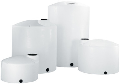
- Vertical bulk tanks with documented insulation-compatible exteriors. Reference N-40164 5000 gallon Norwesco vertical and N-43128 10,000 gallon Norwesco vertical for the bulk-storage end of the cold-climate envelope. Both XLPE construction with smooth-wall exteriors that accept conventional fiberglass or rigid-foam insulation packages.
- Snyder Industries XLPE Captor double-wall: the secondary containment of the double-wall design provides additional thermal mass that smooths cold-climate operation and gives the heat-trace controller more margin during fast ambient excursions. Reference SII-1006600N42 10,000 gallon XLPE Captor.
- Smaller tanks where heat-trace is the right protection level and full insulation enclosures would be overkill. Reference N-41867 25 gallon for laboratory and small-batch applications where a single self-regulating cable wrap and a thermostatic controller are sufficient.
The procurement conversation should include the heat-trace package as a separate engineered scope, with the controller architecture, insulation R-value target, and commissioning plan documented before the tank ships. List pricing on the BC product page is the starting point; LTL freight to your ZIP and the heat-trace system installation are quoted separately. Reference the freight estimator or call 866-418-1777 to coordinate the packaged scope.
10. The Operations Discipline Conclusion
Heat-trace control panel architecture is the engineering decision that separates a tank that survives the first cold snap from a tank that fails it. The bimetallic thermostat works for low-consequence piping. The electronic on-off controller is the workhorse for most bulk tank freeze-protection. The PID controller pays off where temperature precision or multi-zone balance matters. The redundant sensor architecture survives single-point failures that strand the simpler designs. The ground-fault protection meets code and survives cable damage that would otherwise become a hazard.
The mistakes that strand operations are not exotic. Single-sensor designs that fail when the sensor drifts. Two-wire RTD circuits that read wrong as cable length grows. Field-improvised heat-trace terminations that leak current. Non-watertight junction boxes that corrode through the third winter. None of these failures require novel engineering to prevent; all of them require the discipline to specify the system at the right level of sophistication and to commission it correctly the first time.
OneSource Plastics ships the polyethylene tanks that are the foundation of cold-climate storage installations across all 5 brands — Norwesco, Snyder, Chem-Tainer, Enduraplas, Bushman — with shell construction documentation, fitting layouts, and dimensional drawings that the heat-trace contractor needs to design the cable coverage and the controller architecture around. List pricing by SKU is on the product page; LTL freight to your ZIP is quoted separately via the freight estimator or by phone at 866-418-1777. For related cold-climate engineering see heat-traced manifold and valve-box engineering and tank insulation and heat tracing cold-climate operations.
Recommended Tanks for This Guide
Live pricing, updated automatically · estimate freight to your ZIP.