Heat-Traced Manifold and Insulated Valve Box Engineering for Cold-Climate Tank Installations: Watt-Density Selection, Insulation R-Value Math, Thermostat Control Architecture, and the Field Failure Modes That Kill Winter Operations


Tank shell heat tracing keeps the bulk liquid above its freeze point. The piping manifold downstream of the tank — bulkhead nipple, isolation valve, strainer, transfer pump suction, discharge piping, and any sample or vent legs — does not get the benefit of the bulk thermal mass. A manifold sitting in a cold-climate ambient runs at ambient temperature within minutes of flow stoppage, and the smaller the pipe diameter the faster it freezes. The standard winter-operations failure mode in cold-climate chemical service is not a frozen tank; it is a frozen manifold or a frozen valve box, with the tank still warm and the operator unable to move product through the iced-up downstream geometry.
This article walks the engineering basis for designing a heat-traced manifold and insulated valve box that holds the downstream piping above its freeze point through a worst-case ambient excursion. The disciplines covered: heat-loss math for trace-load sizing, watt-density selection by pipe size, self-regulating vs constant-wattage cable selection, insulation R-value and jacket selection, valve box construction and ventilation, thermostat and ground-fault control architecture, and the four failure modes that recur in field-installed cold-climate manifolds. The references cited are IEEE 515 (industrial heat-tracing standard), IEEE 515.1 (commercial heat-tracing standard), NEC Article 427 (electric heat tracing wiring requirements), ASHRAE 90.1 (insulation thermal performance baselines), ASTM C547 (mineral fiber pipe insulation specification), and manufacturer published cable cut sheets for self-regulating polymer matrix products.
1. Heat-Loss Math for Manifold Trace-Load Sizing
The heat-tracing trace-load requirement is the watt-per-foot heat loss from the bare insulated pipe to the cold ambient at the design minimum temperature. The standard heat-loss model from IEEE 515 Annex A reduces to:
Q = (T_pipe - T_ambient) / R_insulation_per_foot
where Q is heat loss in watts per linear foot of pipe, T values are in degrees Fahrenheit (or Celsius with consistent units), and R_insulation_per_foot is the cylindrical-geometry insulation thermal resistance for the pipe diameter and insulation thickness. The cylindrical R-value differs from the flat-wall R-value because the heat-transfer area increases with radius; the IEEE 515 tables tabulate this for common combinations.
For a representative cold-climate sodium hypochlorite manifold at a Minnesota installation: 3-inch schedule 80 PVC pipe, 2-inch fiberglass insulation, design ambient minus-20 degrees F, target pipe maintenance 50 degrees F. Per IEEE 515 Annex A Table A.1, the heat loss for 3-inch pipe with 2-inch fiberglass at a 70-degree-F delta works out to approximately 9 watts per linear foot. A 30-foot manifold then needs 270 watts of trace cable plus a margin for end terminations, valve heat sinks, and fitting losses. Industry practice is to size cable at 1.25 to 1.5 times the bare-pipe heat loss to cover those losses; for the example, 340 to 405 watts of installed cable.
The trace cable itself is rated by watts per foot at a reference temperature (commonly 50 degrees F pipe). A 5-watt-per-foot self-regulating cable runs at full output at 50 degrees F and self-regulates down as the pipe approaches the cable's stable temperature; a 10-watt-per-foot cable runs hotter at the same conditions. The selection rule is to match the cable's rated output at the design pipe temperature to the calculated heat loss, then verify the cable's stable temperature does not exceed the pipe material's continuous-temperature limit. PVC piping has a 140-degree-F continuous limit; CPVC is 200; HDPE is 140; CPVC is the common choice when 10-watt-per-foot tracing is needed for high-loss runs.
2. Self-Regulating vs Constant-Wattage Cable: When Each Is Right
The two industry-standard heat-tracing cable architectures have different field behaviors and different failure modes.
Self-regulating cable. The conductive polymer core has a positive-temperature-coefficient resistance: as the cable heats up, its resistance rises and current draw drops, naturally limiting output. The cable cannot overheat itself and can be overlapped or cross-tied without burnout. Output varies linearly with pipe temperature: roughly 10 watts per foot at 40 degrees F dropping to 5 watts per foot at 100 degrees F on a 5-watt-rated cable. Self-regulating is the right choice for: variable-temperature service, freeze-protection on liquid lines, manifolds with multiple branch sizes, and anywhere overlap is structurally unavoidable. The cable can be cut to length in the field without changing output behavior.
Constant-wattage cable. A fixed-resistance heating element delivers a near-constant watt output regardless of pipe temperature. Output is set by the manufacturing geometry and is a fixed value at the cable's rated voltage. Constant-wattage is the right choice for: high-temperature process maintenance (200+ degrees F), long pull lengths where self-regulating's voltage drop becomes prohibitive, and single-temperature applications where simple control is acceptable. The cable cannot be cut in the field; it ships as a pre-engineered length.
For cold-climate manifolds in the typical chemical-storage application — freeze protection on a tank-to-pump-to-distribution piping run with mixed pipe sizes and several valves — self-regulating is the default. Constant-wattage is reserved for the unusual cases where temperature maintenance requirements exceed self-regulating's output range or pull lengths exceed roughly 200 feet at standard 120-volt or 240-volt circuits.
3. Insulation R-Value Math and Jacket Selection
The insulation directly governs trace-load and trace-cable cost. Doubling the insulation thickness from 1 inch to 2 inches roughly halves the heat loss; doubling from 2 inches to 3 inches reduces it another 30-35 percent. The diminishing return makes 2 inches the common cold-climate standard and 3 inches the high-performance option.
For 3-inch pipe in design minus-20 ambient with pipe maintenance at 50 degrees F:
- 1-inch fiberglass: 16 watts per foot heat loss. Trace cable 20-24 W/ft installed.
- 2-inch fiberglass: 9 W/ft heat loss. Trace cable 11-14 W/ft installed.
- 3-inch fiberglass: 6 W/ft heat loss. Trace cable 8-10 W/ft installed.
- 2-inch polyisocyanurate: 7 W/ft heat loss (better R than fiberglass per inch).
- 2-inch aerogel: 4 W/ft heat loss (best R-per-inch but 4-6x cost premium).
The jacket protects insulation from water intrusion and physical damage. Aluminum jacketing is the cold-climate default for outdoor exposed pipe; stainless is specified in coastal salt-spray service; PVC jacket is acceptable for indoor heated-space tracing but degrades under UV and is not appropriate for outdoor cold-climate exposure. The jacket seam orientation matters: seams should face downward at horizontal pipe runs to shed water, and seam laps should run at least 2 inches with mastic or tape sealant. A failed jacket seam admitting water reduces the insulation's R-value by 50-80 percent in saturated conditions; the trace cable then has to carry the full uninsulated heat loss and either fails on the design ambient or fails the GFCI ground-fault protection circuit.
4. Valve Box Construction for Cold-Climate Service
Manifold valves cannot be wrapped continuously with trace cable because the valve handle, packing gland, and stem assembly need access. Valves are heat sinks: a 3-inch ball valve has roughly 4 to 5 times the surface area per inch of length compared to bare pipe and runs colder than the adjacent pipe under the same trace load. The standard cold-climate solution is a heated and insulated valve box that encloses the valve, the trace cable terminations, and a small section of upstream and downstream pipe.
Valve box construction discipline:
- Box dimensions: at least 4 inches of clearance around the valve body in all directions, plus 6 inches of upstream and downstream pipe inside the box. A 3-inch valve typically requires a box with internal dimensions of roughly 18 by 14 by 14 inches.
- Box wall material: NEMA 4X fiberglass or stainless steel. Wood is acceptable in indoor heated spaces but is not durable in outdoor exposure.
- Box insulation: 2-inch closed-cell foam glued to interior walls, all six surfaces. Closed-cell prevents condensation absorption and maintains R-value through wet-dry cycles.
- Trace cable inside box: 1.5x the linear pipe length of trace cable, helically wrapped on the valve body and termination piping. The extra cable compensates for the higher heat loss from the valve geometry.
- Box ventilation: a single bottom drain hole, 1/4-inch diameter, to shed any condensation. No top vent — vents allow cold-air convection that defeats the box.
- Box access: hinged and gasketed cover for valve operation. Cover gasket must be rated for outdoor cold-temperature service; standard rubber gaskets harden and lose seal at minus-30 ambient.
- Cable entry: pre-fab strain-relief grommets with sealant. Field-cut entry holes admit cold air and water.
The valve box temperature inside should run within 5 degrees F of the maintained pipe temperature once the trace cable is balanced. Field commissioning should include a thermocouple inside the box during a worst-case-ambient day to verify performance.
5. Thermostat and Ground-Fault Control Architecture
Heat-tracing circuits operate continuously through the cold season, and the control architecture determines both reliability and energy cost.
Ambient thermostat control. A single thermostat senses outdoor ambient and energizes the trace circuit when ambient drops below a setpoint (commonly 40 degrees F). All trace cables on the protected geometry run at full self-regulating output during cold periods. Simplest architecture; lowest cost; highest energy use because cables run when geometry may not need heating.
Pipe-mounted thermostat control. A surface-mounted thermostat on each protected pipe segment energizes the trace cable when pipe temperature drops below setpoint (commonly 40 degrees F). Each segment cycles independently. Higher equipment cost; lower energy cost; better at preventing overheating on segments that warm faster than design.
Process-temperature control. An RTD or thermocouple in a thermowell on each protected line feeds a process controller that modulates the trace circuit. Best performance, highest cost, used on temperature-sensitive chemistries (sodium hypochlorite, hydrogen peroxide) where overshoot or undershoot causes degradation.
NEC Article 427.22 requires ground-fault equipment protection on heat-tracing circuits. The standard implementation is a 30-mA GFEP breaker (not a 5-mA GFCI personnel-protection breaker; the trace-cable application uses equipment protection). A nuisance GFEP trip is the most common winter heat-trace failure mode in the field. Causes: water-saturated insulation creating a leakage path, cable damage at terminations, cable damage from rodent gnawing, and aged cable with degraded jacket integrity. The GFEP trip rate gives the maintenance team a leading indicator of insulation or cable failure; recurring trips on a single circuit warrant insulation R-test and cable megger inspection before another season.
6. Heat-Trace Brand Selection for Cold-Climate Tank Installations
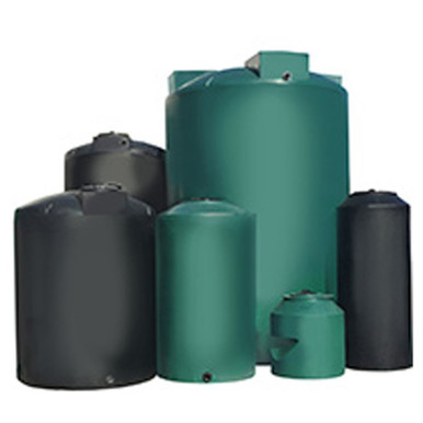
Five-brand catalog tanks are commonly paired with heat-traced manifolds in cold-climate service. The cold-climate-tank product family:
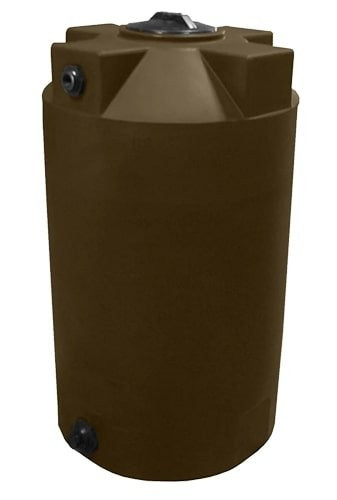
- Norwesco vertical chemical storage: typical cold-climate freeze-protection target. Reference N-40146 1,500 gallon for moderate-volume sodium hypochlorite or sulfuric service; N-40164 5,000 gallon for bulk municipal water-treatment storage; N-43128 10,000 gallon for industrial scale.
- Snyder Captor double-wall: annular containment is itself a cold-climate consideration because the annular space is unprotected by trace cable on the inner shell. Reference SII-5990102N42 1,000 gallon and SII-5490000N42 1,550 gallon.
- Norwesco cone-bottom: stand-mounted cone geometry leaves the manifold and pump suction exposed below the tank. Reference N-43852 1,000 gallon 45-degree cone; the cold-climate manifold runs from the bottom-center outlet.
- Norwesco doorway and water tanks: outdoor water service; reference N-44800 100 gallon doorway and N-41500 1,000 gallon; freeze protection on the dispense manifold is the typical configuration.
- Bushman water: rural water reserve where heat-traced dispense piping runs from the tank to the distribution point. Reference BM-WW-1500-GL-NAT 1,500 gallon.
The tank itself contributes thermal mass that buffers against short ambient excursions. A 5,000-gallon tank with 50-degree-F bulk liquid loses on the order of 1 degree F per 24 hours in a minus-20 ambient with 2-inch insulation; the tank sees a slow temperature drift while the unprotected manifold downstream freezes in 30-90 minutes. The engineering priority is the manifold and valve geometry, not the tank shell.
7. Field Failure Modes That Recur Each Winter
The four heat-trace failure modes that kill cold-climate operations:
Failure mode 1: water-saturated insulation. A jacket seam fails; rain or snowmelt enters; insulation soaks; effective R-value drops 60-80 percent; trace cable cannot deliver enough watts to overcome the elevated heat loss; pipe freezes despite running trace circuit. Diagnostic: visible icing on the jacket exterior, increased GFEP trip rate, infrared thermal imaging shows a cold band along the saturation pattern. Corrective action: full re-jacket or replace the saturated insulation segment, verify seam integrity at all directional changes.
Failure mode 2: cable damage at terminations. Trace cable terminations are stress points. Field installations with crimped lugs, untaped end-seal kits, or nicked jackets at fitting transitions develop ground-fault currents over 1-3 winters. Diagnostic: GFEP trip immediately on cold-weather circuit energization. Corrective action: replace end-seal kits with manufacturer-specified components, re-terminate with proper strain relief, verify with a cable megger before re-energizing.
Failure mode 3: thermostat sensor location error. A pipe-mounted thermostat installed on the warm side of a heat sink (e.g., near a flange that conducts heat from a warmer line) sees a higher temperature than the rest of the protected geometry; cable cycles off when sections downstream are still cold. Diagnostic: localized freezing at points distant from the thermostat. Corrective action: relocate sensor to a representative cold point, or add a second thermostat for the cold zone.
Failure mode 4: valve-box ventilation defect. A box installed with a top vent or with an ungasketed cover admits cold-air convection. Box interior runs at near-ambient temperature; valve and inside-box piping freeze. Diagnostic: ice buildup inside the box on a worst-case-ambient day. Corrective action: seal vent, replace gasket, verify drain is not plugged with debris.
8. Commissioning and Annual Verification Protocol
The trace circuit is not done at installation; it has to be commissioned and re-verified annually.
Commissioning checklist (at install):
- Megger test of trace cable insulation resistance: minimum 20 megohms at 1,000 VDC.
- Continuity test of cable bus wires: full circuit length, both bus conductors.
- Energize and verify current draw within manufacturer's expected range for measured ambient.
- GFEP trip test: simulate ground fault, verify breaker trips at 30 mA in less than 50 ms.
- Thermostat setpoint verification: thermostat trips on at setpoint plus 1 degree F, off at setpoint plus 6-8 degrees F (typical hysteresis).
- Cold-day commissioning: run circuit through a representative cold-day ambient and verify pipe maintenance temperature with infrared imaging or surface thermocouples at 5-10 representative points.
Annual pre-winter checklist:
- Visual inspection of jacket integrity at all seams, directional changes, valve boxes, and terminations.
- Re-megger cable insulation resistance; trend against commissioning baseline. Drop of more than 50 percent indicates aged insulation or moisture intrusion.
- GFEP function test: simulate ground fault, verify breaker trip.
- Energize circuit at first cold-weather day and verify current draw within expected range.
- Thermostat function test: verify setpoint accuracy with a calibrated reference.
The annual protocol takes 4-8 hours per major manifold and is the difference between a winter-running operation and a winter-frozen operation. Skipping the protocol on an aged trace system is the most common root cause of mid-winter operational shutdowns in cold-climate chemical service.
9. Cost-Benefit Framework for Trace Investment
Heat tracing is a capital investment with an ongoing energy operating cost. The decision framework:
- Capital cost: trace cable plus insulation plus jacket plus valve boxes plus thermostats plus GFEP breaker plus installation labor. For a 30-foot 3-inch manifold: roughly $1,500 to $3,500 installed depending on insulation thickness and box count.
- Annual energy cost: trace circuit running 4-6 months at 8-12 watts per foot average output. For a 30-foot manifold at 10 W/ft averaged over 5 cold months at 8 hours-per-day equivalent (the cable cycles at lower duty cycle): roughly 1,000-1,500 kWh per year, or $120-$200 at $0.12/kWh.
- Failure cost avoided: a frozen manifold that splits costs the chemical loss, the cleanup and SPCC reporting, the downtime, and the repair. A typical cold-climate chemical-tank manifold freeze-and-split incident runs $5,000 to $40,000 in direct costs depending on chemistry and spill containment.
The ROI math is straightforward for any cold-climate chemical service: the annualized capital plus operating cost of trace heating is dominated by the avoidance of a single freeze incident over the system life. Heat tracing is not optional in cold-climate chemical service; it is a baseline engineering deliverable that has to be designed, commissioned, and maintained.
OneSource Plastics ships chemical-storage tanks across all 5 brands paired with manufacturer cut sheets, and our engineering team supports cold-climate freeze-protection consultation for the manifold and valve-box geometry downstream of the tank. List pricing by SKU is published on each product page; LTL freight to your ZIP is quoted separately via the freight estimator or by phone at 866-418-1777. For Snyder Captor double-wall storage with annular-space heat-trace consideration, see also our Captor SPCC compliance article. For broader cold-climate planning see freeze protection winter guide and trace cost-benefit by climate zone.
Recommended Tanks for This Guide
Live pricing, updated automatically · estimate freight to your ZIP.