Solar Thermal Pre-Heat Buffer Tank Engineering With Polyethylene Storage: Thermosiphon Loop Physics, Stratification Discipline, ASTM D1998 Temperature Limits, and the Heat-Exchanger Architecture for Agricultural Hot Water


A solar thermal collector array generates hot water during sunny periods and produces nothing at night or under heavy clouds. The standard architecture for matching this intermittent supply to a continuous-demand process — a dairy parlor sanitation system, a greenhouse heating loop, an industrial wash-down operation, a commercial laundry, a small-system process boiler pre-heat — is a buffer tank that stores solar-heated water for use during low-collection periods. The conventional buffer tank is a glass-lined steel pressure vessel rated to 150 psi at 200 degrees F. The polyethylene-tank alternative is appropriate in a specific subset of applications: open-loop or atmospheric-pressure systems, low-pressure recirculation loops, and pre-heat (rather than primary-storage) configurations where the tank operates well below polyethylene's temperature limits.
This article walks the engineering basis for using a polyethylene tank in a solar pre-heat buffer role. The disciplines covered: ASTM D1998 polyethylene temperature limits and how they constrain the design, thermosiphon loop physics and the natural-circulation conditions, stratification discipline and the dip-tube and outlet-port engineering that maintains it, heat exchanger architecture (immersed coil vs external plate vs jacket), freeze protection on the collector loop and the tank, and the system control architecture that keeps the tank within polyethylene's operating envelope. References cited are ASTM D1998 (rotationally molded polyethylene tank specification, including temperature limits), ASHRAE Handbook HVAC Applications (solar thermal systems chapter), SRCC OG-300 (Solar Rating and Certification Corporation operating guidelines), and the manufacturer published temperature limits for the specific tank product.
1. ASTM D1998 Polyethylene Temperature Limits
ASTM D1998 is the controlling specification for rotationally molded polyethylene storage tanks. The standard tabulates the design temperature ratings:
- Standard cross-linked polyethylene (XLPE): continuous service temperature 100 degrees F (37.8 C); short-term excursion 130 degrees F (54.4 C).
- Standard high-density polyethylene (HDPE): continuous service temperature 100 degrees F (37.8 C); short-term excursion 120 degrees F (48.9 C).
- High-temperature variants: some manufacturers offer high-temperature-rated polyethylene with continuous service to 140-160 degrees F (60-71 C); these are specialty products and not interchangeable with standard tanks.
The temperature rating is not arbitrary. Above the rated temperature, polyethylene loses tensile strength rapidly: HDPE at 130 F has approximately 60 percent of its 70 F yield strength; at 150 F, approximately 35 percent. The hoop stress generated by the hydrostatic head of the stored water remains constant, so an undersized wall thickness designed for 70 F service will fail at 130-150 F via creep rupture. Manufacturers tabulate "service factor" by temperature in their literature; the engineer multiplies the room-temperature wall thickness requirement by the temperature service factor to size the wall for elevated service.
For solar pre-heat applications, the design constraint is to maintain the buffer tank at or below 100 F continuous, with brief excursions below 130 F acceptable for standard XLPE. Pre-heat (raising water from 50-60 F to 90-100 F before delivery to a final water heater) fits this envelope easily. Primary solar storage (raising water to 140-180 F for direct use) does not fit a standard polyethylene tank and requires either high-temperature polyethylene or a different tank material.
2. Thermosiphon Loop Physics and Natural Circulation
A thermosiphon loop circulates water between the solar collector and the buffer tank without a pump. The driving force is the density difference between hot water (in the collector and the riser pipe leaving the collector) and cold water (in the buffer tank and the return pipe to the collector). Hot water rises by buoyancy; cold water falls; circulation establishes naturally as long as the geometry supports it.
The geometric requirements for thermosiphon to work:
- Collector below tank: the bottom of the buffer tank must be above the top of the collector, typically by at least 1 foot of vertical separation. The cold-water return falls from the tank bottom to the collector inlet by gravity; the hot-water riser rises from the collector outlet to the tank top.
- Continuous slope: no horizontal runs in the riser or return that allow air to collect. Air pockets break the thermosiphon flow.
- Adequate pipe diameter: the friction loss at thermosiphon flow rates is much smaller than at pumped flow rates. A 1-inch line in a typical 60-square-foot residential collector establishes flow on the order of 0.5-1.5 GPM at full insolation.
- Riser and return port locations on the tank: hot-water return enters the tank at the upper portion (typically 75-85 percent of tank height); cold-water draw to the collector exits at the bottom (the lowest accessible port).
A correctly configured thermosiphon loop runs with no electrical power, no pump, no controls. The system self-regulates: hotter collector means stronger buoyancy means faster flow; cloud cover slows the flow; nighttime stops the flow. For systems where electrical power is limited (rural agricultural sites, off-grid greenhouses), the absence of pump-driven control architecture is the primary operational advantage.
The trade-off is performance limits. Thermosiphon flow rates are 10-30 percent of typical pumped flow rates, so heat transfer to the tank is correspondingly slower. A pumped solar system can charge a buffer tank from ambient to setpoint in 2-4 hours of sun; a thermosiphon system takes 4-8 hours for the same delta. For applications where the use cycle is long (overnight storage for next-morning use), thermosiphon is adequate. For rapid recovery (high-frequency wash-down or sanitation cycles), pumped circulation is required.
3. Stratification Discipline: The Buffer Tank's Critical Design Feature
A buffer tank with effective stratification stores warm water at the top and cold water at the bottom with a thin transition layer between. Stratification matters because the operational use draws hot water from the top and the collector return enters at the top: the system delivers the hottest stored water to the use point, and the collector loop receives the coldest water for maximum collector efficiency.
Stratification destroyers and how to engineer them out:
- Bulk mixing during fill or draw: a high-velocity inlet jet drives turbulent mixing through the tank. Engineering response: a stratification diffuser at the inlet, sized to reduce inlet velocity to 0.1-0.3 ft/s. Standard diffusers are perforated plates, baffle structures, or concentric pipe sections that radially distribute the inlet flow.
- Convective mixing from temperature gradients: a tank shell at outdoor ambient temperature loses heat from the top portion; the cooled top water sinks and mixes with mid-tank water. Engineering response: good external insulation (R-15 or higher) and minimization of tank-shell thermal short-circuits.
- Heat-exchanger return placement: a return jet placed in the wrong vertical position introduces hot or cold water into the wrong stratified layer and disrupts the stratification. Engineering response: stratifying inlets that allow the return water to find its own density-matched layer rather than entering at a fixed point.
- Operational recirculation: any pumped recirculation through the tank that draws and returns from different layer heights mixes the layers. Engineering response: design the recirculation to draw and return at the same height when possible, or schedule the recirculation to minimize mixing during periods of high demand.
A stratified buffer tank can deliver 70-90 percent of its bulk-stored heat at the design hot-water temperature; an unstratified (well-mixed) tank delivers only 50-60 percent because the bulk temperature is the average of stored hot water and infiltrated cold water. The stratification engineering is the difference between a 30 percent and a 70 percent useful storage efficiency.
4. Heat Exchanger Architecture: Immersed Coil vs External Plate vs Jacket
A polyethylene tank cannot directly contain pressurized solar collector water in most applications because the tank is typically atmospheric-pressure rated. The collector loop runs at 30-50 psi to maintain water phase against the elevated collector temperatures and to circulate adequately; the tank is at zero gauge pressure. The interface is a heat exchanger.
The three standard heat-exchanger architectures:
Immersed coil heat exchanger. A coil of stainless steel or copper tubing inside the tank, plumbed to the pressurized collector loop. The collector water flows through the coil; tank water surrounds the coil. Heat transfers from the coil to the tank water by natural convection. Advantages: simple, no external pump on the tank side, no separate vessel. Disadvantages: heat-transfer rate is limited by the coil surface area and the natural-convection film coefficient; a large coil takes significant tank volume; tube-to-tank temperature delta of 10-15 F is typical even at maximum collector output.
External plate heat exchanger. A plate-and-frame or brazed-plate heat exchanger plumbed in a pumped recirculation loop between the tank and the collector. Tank water is pumped through one side; collector water through the other side. Advantages: high heat-transfer rate, compact installation, easy to clean and replace. Disadvantages: requires a tank-side pump (cannot be thermosiphon on the tank side), plumbing complexity, additional electrical load.
Tank-jacket heat exchanger. A jacket around the outside of the tank, with collector water circulating in the jacket. Heat transfers through the tank wall to the stored water. Advantages: no internal coil takes tank volume; simple plumbing. Disadvantages: poor heat-transfer rate because polyethylene's thermal conductivity is low (about 0.4 W/m-K, two orders of magnitude below copper); the jacket must be sized substantially to compensate for the poor wall conductivity. Practical for low-power applications only.
For the polyethylene-buffer-tank pre-heat application, the immersed-coil architecture is the typical choice. The coil is sized with adequate surface area (typically 2-4 square feet of coil per gallon of tank capacity per kW of collector output) and the tank-side flow is natural convection. The collector-side pump is the only electrical load on the system, and the loop runs at modest pressure (30-50 psi) on the coil side.
5. Freeze Protection on the Collector Loop and Tank
The solar collector loop is exposed to outdoor ambient and can freeze in cold-climate operation. The standard freeze-protection architectures:
- Drain-back system: the collector loop drains to a small reservoir at low-flow conditions or shutdown. The drained loop has no water to freeze. Requires the tank-side or reservoir-side to be inside the heated building envelope. Compatible with thermosiphon flow once the loop is filled and operating.
- Closed-loop with antifreeze: the collector loop contains a propylene glycol or ethylene glycol mixture. The mixture circulates between the collector and the heat exchanger; tank water (potable or process water) is on the other side of the heat exchanger and never sees the antifreeze. Standard architecture for residential and small commercial systems.
- Drain-down system: in shutdown, the collector loop drains to atmospheric drain or to a holding tank. Less common than drain-back due to water consumption and the thermal shock of repeated drain-fill cycles.
For the polyethylene buffer tank itself in cold-climate operation: the tank stays inside a heated structure (mechanical room, agricultural barn, greenhouse) where it does not see freezing. If outdoor placement is unavoidable, the tank requires insulation and a backup heat source (electric immersion or boiler-loop coil) to prevent freezing during low-collection periods. Freezing the buffer tank is catastrophic — water expanding on freezing splits the tank wall and causes total loss of contained volume.
6. Tank Selection for Solar Pre-Heat Buffer Service
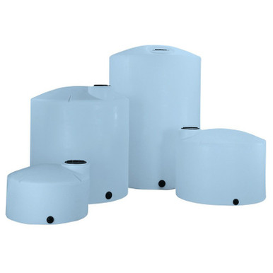
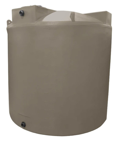
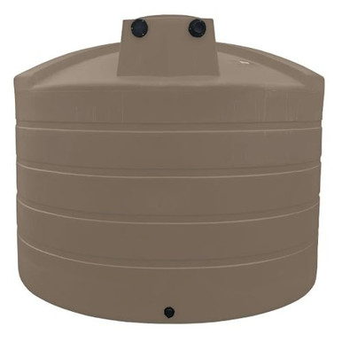
The 5-brand polyethylene catalog includes products that pair with solar pre-heat applications in agricultural, greenhouse, and small-commercial settings:
- Norwesco vertical water storage: the standard atmospheric water storage tank. Reference N-41500 1,000 gallon for a residential or small agricultural pre-heat buffer; N-40164 5,000 gallon for larger agricultural sanitation systems or commercial laundry. The tank is sized to provide overnight buffering of the day's solar heat collection.
- Norwesco doorway water tanks: the smaller-format water tank fits in mechanical-room doorways and tight-clearance retrofit installations. Reference N-44800 100 gallon doorway for small system pre-heat or for a greenhouse hydronic pre-charge tank.
- Bushman water: agricultural water reserve where solar pre-heat reduces propane or electric water-heater consumption for livestock washdown and milking parlor sanitation. Reference BM-WW-1500-GL-NAT 1,500 gallon.
The polyethylene tank must be configured with the appropriate ports for the solar architecture: a top port for hot-water return from the collector loop or heat exchanger, a bottom or low-side port for cold-water draw to the collector, a high-side port for hot-water draw to the use point, and an opening or top port for atmospheric vent. The fittings are standard polyethylene tank bulkhead fittings with the chemistry-appropriate gasket material (EPDM or silicone for hot water service).
7. System Control Architecture and Temperature Limits
The control architecture keeps the tank within the polyethylene temperature envelope and manages the use-side delivery:
- Tank top temperature sensor: RTD or thermistor at the upper portion of the tank, where temperature is highest. Used to disable the collector loop if tank top reaches the upper limit (typically 95-100 F for standard XLPE pre-heat service).
- Collector outlet temperature sensor: measures water leaving the collector. Used to control the differential controller that runs the collector loop pump (in pumped systems) or to monitor performance (in thermosiphon systems).
- Differential controller: compares collector outlet temperature to tank temperature. Energizes the collector loop pump when collector is at least 8-12 F warmer than tank; de-energizes when delta drops below 3-5 F. Implemented in dedicated solar controllers or in a building automation system.
- Tempering valve at the use point: mixes pre-heated tank water with cold water to deliver a setpoint temperature regardless of tank temperature variation. Standard ASSE 1017 or ASSE 1070 thermostatic valve.
- High-limit interlock: hard-wired thermal switch at the tank top set to disable the collector loop at the polyethylene short-term excursion limit (typically 120-130 F). Independent of the differential controller; serves as a backup against control failure.
The high-limit interlock is the safety-critical control. A failure of the differential controller (stuck pump, failed sensor, software bug) can drive the tank above its temperature limit; the high-limit thermal switch is an independent device that prevents this. Hard-wired logic, not software-based; field-tested annually with a calibrated reference.
8. Energy Performance and Sizing Math
The buffer tank size is dictated by the energy balance between collector output and use demand:
- Collector output: rated collector area times the SRCC OG-300 rated daily energy at the design irradiance. A 60-square-foot flat-plate collector on a sunny summer day in mid-latitude USA produces roughly 30,000-50,000 BTU per day.
- Use demand: daily volume of hot water times the temperature delta times water specific heat. A dairy parlor washing 100 gallons per day from 50 to 110 F uses 60 degrees times 100 gallons times 8.33 lb/gallon = 50,000 BTU per day.
- Buffer storage: tank volume to provide carryover from peak collection (midday) to peak use (often early morning or late evening). Standard sizing is 1.5-2 days of average use. For the dairy example: 2 days at 100 gallons = 200 gallons of effective storage; with 30 percent stratification efficiency loss, 300-gallon nominal tank capacity.
- Pre-heat fraction: the percentage of total heating load the solar system provides. With a polyethylene pre-heat configuration capping tank temperature at 100 F, the pre-heat fraction is typically 40-70 percent for hot-water applications with delivery temperature 110-120 F. The remaining heating is done by a downstream conventional water heater (propane, electric, or natural gas).
The economic case for solar pre-heat with a polyethylene buffer tank is driven by displaced fuel cost. For a 50,000-BTU-per-day dairy washdown with 60 percent solar fraction, the displaced energy is 30,000 BTU per day or 11 MMBTU per year; at $1.50 per gallon propane (90 MBTU per gallon), that is roughly $180 per year of displaced fuel. The pre-heat system capital (collector, plumbing, tank, controls) typically runs $4,000-$10,000 installed; payback periods of 8-15 years are common at typical fuel prices, with shorter payback at higher fuel prices or in regions with favorable solar resources.
9. The Boundary Where Polyethylene Stops Being the Right Tank
Polyethylene buffer tanks are correct for solar pre-heat applications. They are not correct for primary solar storage where setpoint temperatures exceed 100 F continuous. The boundary cases:
- Primary solar domestic hot water (typical 130-140 F setpoint): standard polyethylene cannot serve as the primary storage tank. Either use a steel pressure-rated tank, or use a polyethylene pre-heat tank ahead of a conventional water heater that finishes the heating to setpoint.
- High-temperature process applications (140+ F): standard polyethylene cannot serve. Specialty high-temperature polyethylene rated for the temperature is one option; FRP or steel is more common.
- Pressure-rated systems (50+ psi): standard polyethylene cannot serve. Pressurized solar systems require steel or FRP pressure vessels; polyethylene is atmospheric-pressure only.
- Combined solar plus space-heating (radiant floor, hydronic): typical setpoints exceed polyethylene limits. Specialty high-temperature tank or steel pressure vessel.
OneSource Plastics ships polyethylene tanks across all 5 brands paired with manufacturer cut sheets, and our engineering team supports application-specific consultation for solar pre-heat configurations within the polyethylene operating envelope. List pricing by SKU is published on each product page; LTL freight to your ZIP is quoted separately via the freight estimator or by phone at 866-418-1777. For broader water-storage context see freeze protection winter guide and foundation pad engineering.
Recommended Tanks for This Guide
Live pricing, updated automatically · estimate freight to your ZIP.