Tank Overflow Port Engineering for Bulk Polyethylene Storage: Plumbing Topology That Routes Spills to Containment, Sizing Math for Worst-Case Inflow Conditions, and the Failure Modes That Turn an Overflow Into a Site Emergency


The overflow port on a bulk polyethylene tank is the single most under-engineered safety feature on the entire tank. The bulkhead fittings get specified, the vent gets sized, the level sensor gets wired into the alarm panel, and then the overflow port gets installed with whatever 2-inch bulkhead fitting the installer had on the truck, plumbed straight to a 90-degree elbow pointing at the ground. When the inevitable overfill happens — the float fails, the operator forgets to close the inlet valve, the supplier delivers more than the tank can hold — the overflow port turns the routine refill into a Tier I reportable spill that hits the ground next to the tank.
This article walks the engineering of overflow port topology, sizing, and routing for bulk polyethylene storage tanks. The references are EPA 40 CFR 112 (Spill Prevention, Control, and Countermeasure Plans), state secondary containment regulations, ASTM D1998 (Standard Specification for Polyethylene Upright Storage Tanks), the manufacturer technical bulletins from Norwesco, Snyder, Chem-Tainer, Enduraplas, and Bushman on overflow port specifications, and API 650 Appendix F as a structural reference for the equivalent steel-tank overflow design. The objective is the engineered overflow system that catches the worst-case overfill, routes it to containment, and never allows the spill to reach the ground.
1. Why the Overflow Port Is the Last Line of Defense
The hierarchy of overfill prevention on a bulk tank installation typically runs in this order: first the operator, who is supposed to monitor the fill operation and stop the inlet at the target level. Second the high-level alarm, which is supposed to alert the operator before the tank reaches the maximum fill point. Third the high-high-level shutoff, which is supposed to close the inlet valve automatically when the alarm is ignored. Fourth, and only fourth, the overflow port, which is supposed to dump the excess liquid somewhere safe when every other safeguard has failed.
The first three safeguards are administrative and electromechanical. They depend on operator attention, sensor calibration, valve actuation, and electrical power. Each of them has a non-trivial failure rate. The overflow port is the only safeguard that is purely passive — gravity routes the excess fluid through the port regardless of whether the operator is paying attention, the sensor is calibrated, or the valve is functional. It is the last line of defense, and like all last lines of defense it must be engineered to actually catch the worst case.
The "engineered" part is what gets skipped. The overflow port is too often treated as a 2-inch hole in the side of the tank near the top, plumbed to a stub of pipe that points down toward the foundation. When the overfill event happens, the excess liquid pours out of the stub directly onto the ground, which is exactly the outcome the entire safety system was supposed to prevent.
2. The Sizing Math — Worst-Case Inflow Rate vs Overflow Capacity
The first calculation in any overflow port design is the sizing of the port itself. The overflow port must be large enough to discharge the worst-case inflow rate without backing up into the tank, because if the overflow restricts faster than the inflow continues, the tank pressurizes and the next failure is rupture or fitting blowout — significantly worse than the original spill scenario.
- Bulk delivery via tanker truck: typical pump-equipped tanker delivers at 100-300 gallons per minute (GPM) into a tank. A vacuum-truck transfer can be slower (50-150 GPM); a centrifugal-pumped delivery from a frac-tank can exceed 400 GPM.
- Process inlet from upstream pump: typically 50-200 GPM depending on the pump rating and the pipe size.
- Rainwater inflow on outdoor tank with open vent or compromised cover: a 1,000-square-foot tank top in a 2-inch-per-hour rainfall accumulates roughly 100 GPM of water inflow. This is rarely the design case but is a non-trivial contributor in storm events.
- Process upset or runaway reaction: for tanks involved in chemical processing, the worst-case inflow may be a runaway reactor discharge that overshoots the design rate by 2-4x.
The design rule: size the overflow port to handle the maximum credible inflow rate with a 50 percent safety margin and the discharge head limited to no more than 6 inches of liquid level above the port centerline. A 4-inch overflow port at 6 inches of head discharges roughly 350 GPM under free-flow gravity drainage, which covers the typical bulk-delivery worst case. A 6-inch overflow port at the same head discharges roughly 800 GPM, which covers nearly any realistic inflow scenario.
The mistake is sizing the overflow port to match the inlet pipe size without checking the actual inflow rate against the gravity discharge capacity. A 2-inch overflow port at 6 inches of head discharges roughly 90 GPM — which is below the typical tanker delivery rate. The tank pressurizes against the partially-restricted overflow, the polyethylene wall flexes outward, and the next failure point is somewhere unintended.
3. The Plumbing Topology — Where the Overflow Liquid Actually Goes
The overflow port location on the tank is one engineering decision; the plumbing routing from the port to the disposition point is a separate and often more important engineering decision. The plumbing topology determines whether the overflow event ends as a contained, recoverable, low-consequence outcome or as a Tier I reportable spill.
- Routing to a secondary containment dike: the standard practice for tanks under SPCC or state secondary-containment regulations. The overflow plumbing exits the tank, slopes downward at a minimum 1/4 inch per foot, and discharges into the secondary containment dike at a point with adequate clearance from the dike wall and any pumps or motors. The dike is sized per 40 CFR 112.7(c) to hold 110 percent of the largest single tank volume.
- Routing to a dedicated overflow catch tank: for hazardous-chemistry installations where the secondary containment is not practical at the required capacity, a separate underground or aboveground catch tank receives the overflow. The catch tank is sized for the worst-case overflow event volume — typically the difference between the high-high level and the tank top, plus a safety margin.
- Routing to a process drain that connects to the site treatment system: appropriate only when the chemistry can be treated by the site system at the worst-case discharge rate. Most process drains cannot handle 300+ GPM without backing up; the overflow then fails the same way as a too-small port.
- Routing to a discharge point at grade with no containment: the configuration that turns every overfill into a reportable spill. This is the configuration that routinely shows up in site walkthroughs and that the SPCC reviewer flags first.
The engineering rule: every overflow port must terminate in a containment that holds the maximum credible overflow volume with margin. The containment may be the secondary dike around the tank, a dedicated catch vessel, or a process system rated for the discharge — but it must exist and it must be documented in the SPCC plan or equivalent site procedure.
4. The Inverted U-Trap and Air-Break Engineering
A subtle failure mode in overflow plumbing is the siphon. If the overflow line slopes continuously downward from the tank port to the discharge point, and the discharge point is below the operating fluid level in the tank, a partial overflow event can prime the line and start a siphon that drains the tank well below the overflow level. The result: the overflow event continues long after the inflow has stopped, and the tank loses far more liquid than the actual overfill.
The engineering remedy is the inverted U-trap (sometimes called a vacuum break or air break) installed at the high point of the overflow plumbing. The inverted U rises above the maximum operating fluid level in the tank, includes a vent or air admittance at the top, and then descends to the discharge point. Air enters the line through the vent during any flow event, which breaks any siphon before it can establish.
The engineering specifications:
- The inverted U-trap top must be at least 4-6 inches above the maximum operating fluid level in the tank. Not at the overflow port elevation — at the actual maximum fill elevation, including any margin for surge during fill events.
- The vent on the inverted U must be sized to break siphon at the design flow rate. A 1-inch vent on a 4-inch overflow line is typically adequate for the gravity-discharge case; the vent should never be smaller than 1/4 of the overflow line diameter.
- The vent must be protected against debris ingress and insect intrusion while still admitting air freely. A bird-screen and a vent cap with downward-pointing aperture work; a fully sealed cap defeats the purpose.
- The plumbing geometry must avoid traps below the inverted U where solids could accumulate. The full path from the tank port to the inverted U should slope upward; the path from the inverted U to the discharge point should slope downward continuously.
The inverted U-trap adds engineering complexity but it converts the overflow system from a potential drain-the-whole-tank failure mode to a self-limiting overflow that stops the moment the inflow stops.
5. Material Selection for Overflow Port Plumbing
The overflow plumbing carries the same chemistry as the tank contents during an overflow event, plus any additional contaminants from the secondary containment. Material selection follows the same compatibility logic as the inlet and outlet plumbing, with a few additional considerations:
- Chemistry compatibility at maximum operating temperature: the overflow line may sit dry for years between events, which means seal materials, gaskets, and elastomeric components age in atmosphere rather than continuously wetted service. The compatibility envelope must include both the wetted-service and the dry-aged-service conditions.
- UV exposure for outdoor installations: the overflow line is typically more exposed to direct sun than the inlet or outlet plumbing because it is at the top of the tank and may run in open air to the containment. UV-stable materials (carbon-pigmented HDPE, painted steel, stainless) are required for outdoor service.
- Freeze tolerance for cold-climate sites: the overflow line that sits dry between events may collect condensation or rainwater that freezes and ice-blocks the line. The engineering options are heat-tracing the overflow path, sloping the line aggressively to drain any accumulated water, or using a flexible material that tolerates ice without rupturing.
- Fire-rating considerations for hydrocarbon and flammable-chemistry service: the overflow line may discharge flammable liquid into a containment that is also exposed to ignition sources. Material selection must consider the fire-resistance envelope; PVC and HDPE are not appropriate for installations where the overflow path crosses a fire-rated boundary.
The default specification for overflow plumbing on neutral-chemistry water and aqueous-solution service is Schedule 80 PVC for indoor and shaded outdoor runs, carbon-pigmented HDPE for sun-exposed outdoor runs, and 304 or 316 stainless steel for hydrocarbon, hot-chemistry, or fire-exposed installations.
6. The Tank Selection That Includes Engineered Overflow Provisions
The overflow port engineering is materially easier when the tank manufacturer provides a documented overflow port location, fitting size, and head-pressure rating. Norwesco, Snyder, Chem-Tainer, Enduraplas, and Bushman each publish technical drawings showing the standard overflow port location and the engineering envelope around it.
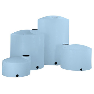
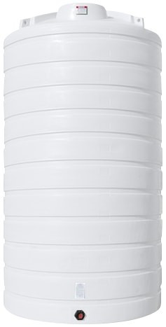
- Vertical bulk tanks with engineered top-side overflow port: reference N-40164 5,000 gallon Norwesco vertical and N-43128 10,000 gallon Norwesco vertical, both XLPE construction with technical drawings showing the standard 2-inch and 3-inch overflow port options at the engineered locations near the dome top.
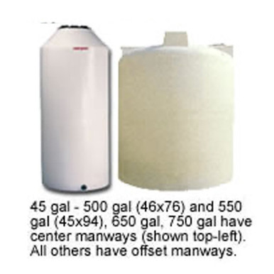
- Cone-bottom tanks where the overflow port location must accommodate the offset cone geometry: reference N-43852 1,000 gallon 45-degree cone; the overflow port specification on these geometries requires the manufacturer technical drawing to verify the relationship between the maximum fill elevation, the dome-top fitting boss, and the overflow port centerline.
- Double-wall containment tanks where the overflow event remains within the secondary wall: reference Snyder Captor double-wall units which include integrated containment that captures any overflow without relying on a separate dike. Models like the SII-1006600N42 10,000 gallon XLPE Captor simplify the entire overflow topology by eliminating the secondary plumbing run.
The engineering brief should include the maximum credible inflow rate, the secondary containment configuration, the overflow disposition strategy, and the climate envelope. The tank manufacturer specification should be verified against this brief before the order is placed; retrofitting an additional or larger overflow port to an installed tank is materially more expensive than specifying the correct port at order time.
7. The Inspection and Test Cadence for Overflow Systems
The overflow system is the safety system that almost never operates. It sits dry for months or years between events. The components age, the plumbing fills with debris or insect nests, the vent air-break gets clogged or painted shut, and the inverted U-trap fills with sediment. By the time the actual overfill event arrives, the overflow system may be partially or fully blocked — and the operator who has never tested the system has no idea.
- Quarterly visual inspection. Walk the overflow plumbing from the tank port to the discharge point. Verify the inverted U vent is clear, the discharge point is clean, the slope is correct, and any thermal-expansion or flexible elements are still articulated.
- Annual flow test. Pour 2-5 gallons of water into the overflow port from above (using a hose or a pump) and verify the water flows freely through the entire plumbing path to the discharge point. Time the discharge to verify the path is not partially blocked.
- Five-year detailed inspection. Disassemble any inline components (strainers, traps, check valves), inspect for corrosion or deposits, replace as needed. Verify the vent screen on the inverted U is intact and not clogged. Re-test flow capacity against the original design specification.
- After any chemistry change. If the tank chemistry changes (different product, different concentration, different temperature), re-verify the overflow plumbing material compatibility and re-inspect for any chemistry-driven degradation in the line.
The maintenance philosophy: the overflow system that has been tested in the last twelve months is the system that works during the incident. The system that has never been tested is a Schrödinger's-overflow that may or may not work, and the only way to find out is to have the incident.
8. Documentation, SPCC Plan, and Regulatory Posture
The SPCC plan required under 40 CFR 112 must include the overflow disposition strategy as part of the spill prevention engineering. The plan typically documents:
- The overflow port location, size, and discharge plumbing routing. A site drawing showing the tank, the overflow port, the plumbing path, and the disposition point (containment dike, catch tank, treatment connection).
- The maximum credible overflow volume. Calculated as the difference between the high-high level alarm setpoint and the tank top elevation, multiplied by the tank cross-section, with a 25 percent safety margin.
- The containment capacity and engineering basis. Volume calculation showing the secondary containment dike or catch tank holds at least 110 percent of the maximum credible overflow event.
- The inspection and test schedule and the responsible parties. Quarterly visual, annual flow test, five-year detailed — assigned to specific roles and tracked in the site maintenance management system.
- The response protocol if an overflow event occurs. Notification, recovery, and reporting procedures including any state and federal reporting thresholds.
The regulatory posture for the site is materially stronger when the SPCC plan documents a properly-engineered overflow system than when the plan is silent on the topic. The first SPCC reviewer who walks the site will check the overflow plumbing against the site drawing; a discrepancy is a finding that goes into the report, and the report goes into the agency record.
9. The Engineering Discipline Conclusion
The overflow port is too often the last item on the tank installation checklist, handled by whichever installer reaches it last with whatever fittings are still on the truck. The result is a passive safety system that exists in concept but does not actually catch the failure mode it was supposed to catch. The engineering remedy is to treat the overflow system as a system: sized for the worst-case inflow, plumbed to a real containment, equipped with siphon-break and air-admittance protection, built from materials compatible with the chemistry and the environment, and tested on a documented schedule.
The cost difference between an engineered overflow system and a 90-degree elbow pointing at the foundation is a few hundred dollars in fittings and a few hours of labor. The cost difference between a contained overflow event and a Tier I reportable spill is everything else: the cleanup, the agency notification, the regulatory penalty, the site reputation. The math favors the engineering every time.
OneSource Plastics ships the polyethylene tank platform that is the upstream end of these overflow designs across all 5 brands — Norwesco, Snyder, Chem-Tainer, Enduraplas, Bushman — with overflow port specifications, dimensional drawings, and technical bulletins that the application engineer needs to design the disposition plumbing. List pricing by SKU is on the product page; LTL freight to your ZIP is quoted separately via the freight estimator or by phone at 866-418-1777. For related installation engineering see tank plumbing system design walkthrough and tank piping support engineering.
Recommended Tanks for This Guide
Live pricing, updated automatically · estimate freight to your ZIP.