Mechanical Seal Selection for Chemical-Service Centrifugal Pumps Tank-Fed: Single Versus Double Seal Architecture, Face-Material Pairings, Flush Plan Selection, and the API 682 Discipline Adapted to Polyethylene Tank Bulk-Discharge Service

The mechanical seal on a centrifugal pump is the dominant pump-failure-mode initiator in chemical service, and seal selection is the engineering decision that determines whether the tank-fed pump delivers the chemistry reliably across years of service or fails monthly with leaks, fires, or environmental releases. The selection problem is multi-dimensional: single seal versus double seal architecture, face-material pairing for the chemistry compatibility, flush plan for cooling and contamination control, and the application of API 682 discipline (originally developed for refinery service) to the smaller-scale polyethylene tank discharge applications that dominate industrial chemistry handling. This article walks the architecture decision tree, the face material pairings by chemistry, the flush plans, and the procurement discipline that produces reliable installations.
The discussion is grounded in API 682 fourth edition guidance, manufacturer literature from major mechanical seal vendors, and field practice for polyethylene tank discharge service across the 5-brand catalog (Norwesco, Snyder, Chem-Tainer, Enduraplas, Bushman). List pricing on each tank product page; LTL freight quoted to your ZIP via the freight estimator or by phone at 866-418-1777.
1. The Single Versus Double Seal Architecture Decision
The first architecture decision in mechanical seal selection is single versus double seal arrangement:
- Single seal architecture. A single mechanical seal places one seal-face pair between the pumped chemistry and the atmosphere. The seal is exposed directly to the chemistry on the inboard side and to the atmosphere on the outboard side. Single seals are simpler, less expensive (typically 200-800 dollars for a 1.5-inch shaft seal), and have a lower drag (less parasitic horsepower). They are appropriate for benign chemistry where a small seal leak is acceptable: water, dilute brines, urea solution, glycol coolants.
- Double seal architecture. A double mechanical seal places two seal-face pairs in series, with a barrier or buffer fluid between them. The inboard seal contains the process chemistry; the outboard seal contains the barrier fluid and isolates the inboard seal from the atmosphere. Double seals are required for hazardous chemistry (acids, oxidizers, hydrocarbons, toxic solutions) where any leak to atmosphere is unacceptable. Cost is 2-4x a single seal of the same size.
- Pressurized double seal (API Plan 53). The pressurized double seal uses a barrier fluid pressurized above the process pressure. Any leak across the inboard seal flows from barrier into process (not the other way), preventing process leakage to atmosphere. The pressurized arrangement is preferred for high-hazard chemistry where containment is critical.
- Unpressurized double seal (API Plan 52). The unpressurized double seal uses a buffer fluid at lower pressure than process. A small inboard leak shows up as buffer fluid contamination, providing leak detection while still containing the chemistry between the seals. The unpressurized arrangement is acceptable for lower-hazard chemistry and is mechanically simpler than the pressurized variant.
- Tandem versus back-to-back face arrangement. Double seals can be arranged with both inboard faces facing process (back-to-back) or with the seals stacked in tandem. Back-to-back is preferred for flashing services and for high-temperature chemistry; tandem is preferred for ease of maintenance and for buffer fluid management. The arrangement choice depends on the chemistry phase behavior and the maintenance discipline.
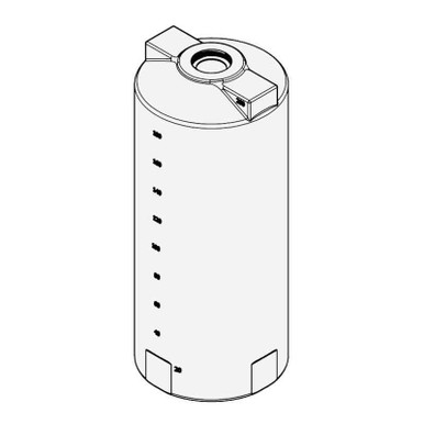
- Reference application for tank discharge pumping. For a tank-fed centrifugal pump on N-40164 5000 gallon Norwesco vertical handling sodium hypochlorite, the appropriate seal is a pressurized double seal with EPDM elastomers and silicon-carbide faces, with a glycol-water barrier fluid in API Plan 53A configuration. The same tank handling water for irrigation accepts a single seal with carbon-ceramic faces and Buna-N elastomers.
The single-versus-double decision is the highest-impact architectural choice in seal selection. The decision is driven by the chemistry hazard level, the regulatory regime, and the operational tolerance for seal leaks.
2. Face Material Pairings by Chemistry
Within the chosen architecture, the face material pairing on each seal-face pair drives chemistry compatibility and seal life:
- Carbon vs ceramic face pairing. Carbon (resin-bonded carbon graphite) running against ceramic (alumina or zirconia) is the entry-level face pairing. The carbon face acts as a sacrificial bearing surface; it wears slowly against the harder ceramic. The pairing handles water, mild brines, dilute caustic, and similar benign chemistry. It is the lowest-cost face combination (40-60 percent cost premium over a stuffing-box packing arrangement).
- Carbon vs silicon carbide face pairing. Silicon carbide is harder than ceramic and offers better thermal conductivity. Carbon-vs-SiC handles more aggressive chemistry than carbon-vs-ceramic, including dilute acids, hypochlorite at moderate concentration, and some solvents. Cost is 50-80 percent above carbon-vs-ceramic.
- Silicon carbide vs silicon carbide face pairing. SiC-vs-SiC eliminates the sacrificial carbon and produces a hard-vs-hard face pair. The pairing requires excellent face flatness and adequate face cooling to avoid heat checking; it handles aggressive chemistry including concentrated acids, oxidizers, and abrasive slurries. Cost is 2-3x carbon-vs-ceramic.
- Tungsten carbide vs silicon carbide face pairing. WC-vs-SiC is a hard pairing with different wear characteristics than SiC-vs-SiC. The asymmetry produces a defined wear pattern and is preferred for some abrasive applications. WC handles chemistry with limited oxidation potential; aggressive oxidizers attack tungsten and the WC face is unsuitable.
- Diamond-coated face pairing. Polycrystalline diamond (PCD) coating on a SiC base provides extreme hardness and chemistry compatibility. PCD-vs-SiC or PCD-vs-PCD handles concentrated acids, severe oxidizers, and abrasive slurries with seal life multiples of standard hard faces. Cost is 5-10x carbon-vs-ceramic; the technology is reserved for severe service.
- Elastomer secondary seal selection. The mechanical seal includes secondary elastomer seals (O-rings, wedges) that confine the chemistry within the seal cavity. Elastomer compatibility is selected by chemistry: Buna-N for water and dilute brines, EPDM for hypochlorite and oxidizers, Viton for acids and hydrocarbons, FFKM for severe service. The elastomer is often the limiting compatibility component on an otherwise capable face pairing.
The face material pairing is selected from the chemistry compatibility chart cross-referenced with the seal vendor's published service data. Most tank discharge applications land at carbon-vs-SiC or SiC-vs-SiC depending on chemistry severity.
3. Flush Plan Selection (API Plan Numbers)
API 682 codifies seal flush arrangements as numbered plans, and the appropriate plan for a tank-fed centrifugal pump depends on the chemistry, the tank suction conditions, and the seal architecture:
- API Plan 11 (recirculation from discharge to seal chamber). The simplest flush arrangement takes a small flow from the pump discharge, throttles it through an orifice, and routes it to the seal chamber. The flush flow cools the seal faces and flushes contaminants out of the seal chamber. Plan 11 is appropriate for clean process service where the discharge fluid is the appropriate flush medium. It is the default for water-service single-seal tank discharge pumps.
- API Plan 13 (recirculation from seal chamber to suction). Plan 13 reverses the flow direction: flush from seal chamber back to pump suction. The arrangement is preferred for vertical pumps and self-priming applications where Plan 11 cannot deliver clean flush flow. It introduces additional thermal coupling between seal and suction that affects net positive suction head margin.
- API Plan 21 (recirculation through cooler). Plan 21 routes the discharge-to-seal flush through an external heat exchanger that cools the flush before it reaches the seal chamber. Plan 21 is required for elevated-temperature chemistry where direct flush would deliver fluid above the seal temperature limit. It is common for hot-water and process chemistry above 140 F.
- API Plan 23 (recirculation through internal pumping ring and external cooler). Plan 23 uses an internal pumping ring on the seal cartridge to drive flush flow through an external cooler and back to the seal chamber. Plan 23 isolates the seal chamber thermally from the process and is appropriate for severe high-temperature service.
- API Plan 32 (external clean flush from external source). Plan 32 introduces flush from an external source (clean water, compatible solvent) into the seal chamber and overflows back to the process. Plan 32 isolates the seal from contaminated process fluid; it is required for slurry service or abrasive process where the discharge fluid would damage the seal faces.
- API Plan 53 (pressurized barrier fluid for double seals). Plan 53 (with sub-variants A, B, C) provides pressurized barrier fluid to the cavity between dual seal faces. The barrier system includes a pressurized reservoir, level monitoring, and pressure regulation. Plan 53 is the standard for hazardous service double seals.
- API Plan 54 (external pressurized barrier fluid system). Plan 54 takes the pressurized barrier system off the pump and locates it remotely with circulation back to the seal. Plan 54 is preferred for very large pumps or for installations where multiple pumps share a barrier fluid system.
- Reference flush plan for hypochlorite tank discharge. A centrifugal pump discharging sodium hypochlorite from N-41524 2500 gallon Norwesco at 50 GPM uses a double seal in Plan 53A configuration with a glycol-water barrier fluid, monitoring for leak detection on the barrier reservoir. Single-seal arrangements are not appropriate for hypochlorite service due to the chlorine emission risk on seal failure.
The flush plan selection is the third architectural decision in seal specification. The plan choice is driven by chemistry properties (clean vs slurry, ambient vs hot, benign vs hazardous), the pump configuration, and the seal architecture (single vs double).
4. The Tank Suction Conditions and Seal Reliability
The tank-fed centrifugal pump experiences specific suction conditions that influence seal reliability:
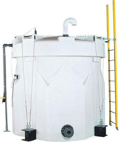
- Tank-bottom outlet hydraulic head. A bottom-outlet tank pump receives positive suction head equal to the liquid column above the suction. For a 5000 gallon vertical tank with 14 feet of liquid column at full, the pump receives roughly 6 PSI suction pressure (varies with chemistry specific gravity). The positive head ensures pump priming and reduces cavitation risk that would otherwise vibrate the seal faces.
- Side-mounted outlet suction profile. A side-outlet tank pump receives lower suction head as liquid level drops, eventually losing suction below the outlet elevation. The varying suction conditions stress the seal during the empty-tank operations; vapor entrainment and dry-running episodes shorten seal life dramatically.
- Suction strainer and filtration. A suction strainer between tank outlet and pump inlet removes debris that would otherwise erode seal faces. The strainer specification (mesh size, material) depends on the chemistry and the expected debris load. For hypochlorite service the strainer is typically PVC or PP construction; for water service stainless steel is acceptable.
- NPSH-available margin and seal cavitation protection. Net positive suction head available (NPSHA) above the pump's required NPSH (NPSHR) prevents cavitation in the impeller eye. Cavitation produces vapor bubble collapse that vibrates the seal faces and accelerates wear. A 3-foot NPSH margin is the field rule of thumb; the seal life is materially better above the margin than below it.
- Pump dry-run protection. Dry-running a centrifugal pump (no liquid in suction) burns up the seal faces in seconds to minutes. Dry-run protection (low-level switch on the tank, suction pressure switch, motor current monitoring) is essential for seal longevity. The dry-run protection should shut the pump down before the suction unloads.
- Reference 1000 gallon for typical tank suction architecture. Reference N-40152 1000 gallon Norwesco vertical as a typical mid-volume tank where the suction architecture decisions apply directly. The bottom-outlet versus side-outlet decision, the strainer selection, and the dry-run protection apply equally on this size class.
The tank suction conditions are upstream of the seal selection but they dominate seal reliability outcomes. A poorly-configured suction with cavitation, dry-run risk, or debris ingress will fail any seal regardless of how well-specified the seal itself is.
5. Installation, Commissioning, and Break-In Discipline
The installation and commissioning protocols on a mechanical seal determine whether the engineered seal achieves its design service life:
- Cartridge versus component seal installation. A cartridge seal arrives pre-assembled with the rotating and stationary faces aligned in a sleeve. Cartridge installation slides the cartridge onto the shaft and bolts it to the pump housing; the field operator does not handle the seal faces. Component seals require field assembly with face alignment and shaft positioning; they are more error-prone but lower cost. Modern best practice favors cartridge seals for chemistry service.
- Face flatness inspection at installation. Even a cartridge seal can be damaged in shipping or handling. Inspection of the face flatness with a monochromatic light source and an optical flat is the gold-standard QC; field practice often substitutes a visual inspection for chips or scratches. Damaged faces are not installed; they are returned to the vendor.
- Shaft sleeve runout measurement. Shaft total indicated runout (TIR) at the seal location should be below 0.002 inches per the API 682 specification. Higher runout produces face wobble that accelerates wear. The runout is measured with a dial indicator before seal installation and corrected (shaft straightening, replacement, or impeller balance) if outside spec.
- Setting the seal on the shaft. The cartridge seal includes a setting clip or fixture that holds the seal in the correct axial position during installation. The clip is removed after the cartridge is bolted to the housing; if the clip remains in place the seal will not function. The clip removal step is the most common installation error.
- Initial flush flow verification. After installation the flush plan flow is verified by observation: the flush line is hot or warm to the touch (cooling flow active), the flush flow indicator shows positive flow, and the seal chamber temperature is within the design range. Verification is done before pump start and again after 1 hour of operation.
- Break-in run protocol. A new seal is run for 1-4 hours at reduced speed or reduced pressure to allow the faces to bed in (microscopic high spots on the carbon face wear off, producing a flatter contact pattern). Aggressive startup at full speed and full pressure can polish-burn the faces and shorten seal life. The break-in period is documented in the commissioning report.
- Reference small tank for small-pump installation. Reference N-44800 100 gallon Norwesco doorway tank as a small-scale installation where smaller pumps and simpler single seals are typical. The installation discipline scales identically with smaller tooling.
The installation discipline is where most seal failures originate. A high-quality seal with poor installation underperforms a low-quality seal with excellent installation. The field training and supervision that produces good installations is the highest-return investment in seal reliability.
6. Failure Mode Analysis and Diagnostic Patterns
Field experience produces a catalog of recurring mechanical seal failure modes with diagnostic patterns:
- Heat-checked face from inadequate cooling. A hard face (SiC, WC, ceramic) running with insufficient cooling reaches face temperatures above the material's thermal shock threshold. The face surface develops a network of fine cracks (heat checks) that initiate spalling and eventual face destruction. The diagnostic is visual: inspection of the failed face shows the characteristic crack network. The fix is flush plan upgrade (Plan 21 or Plan 23) and verification of flush flow rate.
- Polished face from dry-running. A face that has run dry shows a polished or burnished surface with no wear pattern. The friction during dry-running heats the face above material limits and the bonding between carbon particles in a carbon face fails. The fix is dry-run protection (low-level switch, motor current monitoring) and replacement of the polished face.
- Chemical attack on elastomer secondary seal. A failed elastomer (cracked, swollen, dissolved) produces seal cavity leakage independent of the face condition. The diagnostic is removal and inspection of the elastomer; chemistry attack is visible. The fix is elastomer material reselection (Buna to EPDM, EPDM to Viton, Viton to FFKM as severity escalates).
- Chip in face from solid debris ingress. A chip in the rotating or stationary face indicates solid particle ingress through the strainer, the flush, or the suction. The chip propagates and the face loses sealing capability. The fix is suction filtration upgrade and root-cause analysis of the debris source.
- Crystallization on face from chemistry vaporization. Some chemistries (caustic solutions, nitrate salts, urea) crystallize when chemistry vapor reaches a cool surface in the seal cavity. The crystallization stops face rotation or scratches the faces. The fix is heat trace on the seal cavity or flush plan upgrade to dilute the chemistry locally with clean flush.
- Fretting wear on shaft sleeve. A worn impression on the shaft sleeve where the seal O-ring sits indicates fretting wear from face wobble or shaft runout. Fretting damages the sealing surface for the elastomer and produces leakage even with new seal faces. The fix is shaft sleeve replacement and TIR measurement at re-installation.
- Shaft thermal expansion and seal misalignment. A pump operating across wide temperature swings experiences shaft thermal expansion that affects seal axial loading. Modern cartridge seals accommodate small expansion through spring loading; older seal designs with rigid setting can be misaligned by expansion. The fix is seal upgrade to a current cartridge design with expansion compensation.
The failure mode catalog supports rapid diagnosis when a seal fails in service. Most failures fall into one of these patterns and respond to the corresponding fix.
7. Procurement Discipline and Vendor Selection
The procurement of mechanical seals involves vendor selection, specification discipline, and inventory management:
- Major vendor catalog selection. The major mechanical seal vendors (John Crane, Flowserve, EagleBurgmann, AESSEAL, Chesterton) all offer cartridge seals appropriate for chemistry service on tank discharge pumps. Vendor selection is driven by local service availability, parts inventory in regional stock, and engineering support quality. The vendor catalog typically lists model numbers indexed by shaft size, chemistry compatibility, and pressure-temperature rating.
- Specification document discipline. The seal specification document includes: pump model and shaft size, chemistry composition with worst-case impurities, pressure and temperature operating range, flush plan (API Plan number), face material pairing, elastomer selection, expected service life, and acceptance test criteria. The document is the contract between buyer and vendor for the seal supply.
- Spare seal inventory. A site with multiple chemistry-service pumps maintains spare seals matched to each pump. The spare-to-installed ratio is typically 1:3 for critical pumps and 1:5 for non-critical. Spare inventory cost is meaningful (single seals 200-800 dollars, double seals 800-3000 dollars) but the alternative is process shutdown when a seal fails on a critical pump.
- Seal repair and remanufacture. Some vendors offer seal repair services where a worn seal is returned and rebuilt to original specification. Repair cost is typically 40-60 percent of new seal cost. Repair extends the practical service life of the seal investment and reduces the new-seal procurement frequency. Repair quality varies by vendor; reference customers and quality audit are appropriate before committing to a repair vendor relationship.
- Vendor service contract. For critical chemistry-service installations a service contract with the seal vendor provides on-call field engineering for installation, troubleshooting, and failure analysis. The contract cost is typically 5-10 percent of seal procurement spend; the operational value depends on the in-house engineering capability.
- Reference small-tank pump for small-pump procurement. Reference N-40160 325 gallon Norwesco pickup truck tank as a small-scale mobile installation where the pump is typically a small centrifugal or diaphragm pump and the seal selection is simpler. The procurement discipline scales but the seal complexity drops.
The procurement discipline supports the operational discipline. A site that invests in vendor relationships, specification quality, and spare inventory experiences materially fewer pump-seal-driven outages than a site that sources seals reactively as failures occur.
8. The Mechanical Seal Selection Conclusion
Mechanical seal selection for chemical-service centrifugal pumps tank-fed is the engineering decision that most directly determines pump reliability. The architecture decision (single versus double, pressurized versus unpressurized) is driven by chemistry hazard. The face material pairing is driven by chemistry compatibility. The flush plan is driven by chemistry properties and seal architecture. The installation discipline determines whether the engineered seal achieves its design life. The procurement discipline (vendor relationships, specification quality, inventory management) sustains the seal program across decades of operation.
OneSource Plastics ships polyethylene tanks across the 5-brand catalog (Norwesco, Snyder, Chem-Tainer, Enduraplas, Bushman) sized for chemistry-service centrifugal pump installations. Tank selection for any specific application is performed by the customer site engineer with reference to chemistry, flow rates, and pump specification; the seal selection is then matched to the pump and chemistry. List pricing on each product page; LTL freight to your ZIP via the freight estimator or by phone at 866-418-1777. For related engineering see tank-bottom vs side-mount suction and pump priming and dry-run protection.
Recommended Tanks for This Guide
Live pricing, updated automatically · estimate freight to your ZIP.