Sloped-Bottom Tank Tilt Verification and Drain Protocols: 3-Degree, 5-Degree, and 7-Degree Geometry Field Acceptance with Residual Heel Math
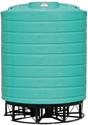
Sloped-bottom polyethylene tanks are specified when the operator needs to drain to a low residual heel without a cone-bottom stand structure. The geometry is straightforward: the tank floor is integrally molded with a slope toward a single low-side outlet, and the slope angle dictates how much liquid remains in the tank when the outlet stops flowing. The common rotomolded slope angles are 3 degrees, 5 degrees, and 7 degrees, and the differences between them are operationally significant. A 3-degree tank holds back roughly twice the residual heel of a 7-degree tank in the same diameter; a 5-degree tank sits in the middle. This article walks the field acceptance methodology for verifying that an installed sloped-bottom tank actually delivers the slope it was specified to deliver, the residual heel math that quantifies what each slope angle leaves behind, and the drain protocol discipline that converts the geometry into a defensible operational outcome.
References cited: ASTM D1998 standard specification for polyethylene upright storage tanks (the dimensional tolerance window for rotomolded geometry); manufacturer published cut sheets for Norwesco, Snyder, Enduraplas, Chem-Tainer, and Bushman sloped-bottom product lines; OSHA 1910.106 atmospheric storage discipline for drain-down sequences; and the consolidated industry field-installation data on level-survey methodology for tank pads. The geometry math below is straightforward trigonometry; the field implications come from the tolerance stack between mold-cycle variation, pad levelness, and bulkhead height-of-take-off.
1. Why the Slope Angle Number Is Not the End of the Story
A 5-degree sloped-bottom tank cut sheet says "5-degree slope to outlet." What the cut sheet does not say is that the slope is referenced to the tank's molded centerline, not to the absolute vertical reference frame in the field. If the pad is out of level by 1 degree away from the slope direction, the effective slope on the wetted floor is 4 degrees, not 5. If the pad is out of level by 1 degree toward the slope direction, the effective slope is 6 degrees. Pad levelness compounds with the molded slope, and the operational consequence shows up as residual heel after a drain-down.
The field implication is that the slope number from the cut sheet is a starting point for design, not an as-installed performance specification. The as-installed performance has to be verified by a level survey that measures the actual angle of the tank floor relative to true horizontal, and the residual heel after a drain has to be measured directly under operating conditions. Any sloped-bottom installation that has not been level-surveyed and drain-tested has not been commissioned; it has only been delivered.
The second point that the cut sheet does not say is that the bulkhead outlet is mounted at a finite height above the lowest point of the floor. The vertical offset from the lowest interior point to the centerline of the outlet bore is typically 1 to 2 inches on a small sloped-bottom tank and can reach 3 inches on a larger one. That offset is dead heel that no slope angle can drain. The 3, 5, or 7 degrees only governs how much of the wetted area drains down to the outlet level; the volume below the outlet is permanent residual unless a sump or pump-out provision is added.
2. The Residual Heel Math by Slope Angle
For a cylindrical tank of diameter D and a flat-bottom slope at angle theta toward a single low-side outlet at the wall, the residual heel volume above the outlet plane (assuming the outlet centerline is at the lowest point of the slope) approximates a triangular wedge integrated around the cylinder. The closed-form approximation for a thin wedge is:
Heel volume = (D^3) * tan(theta) / 12 (in consistent length units; output in cubic units)
For a 96-inch (8-foot) inside diameter tank, the heel volume by slope angle:
- 3 degrees: tan(3) = 0.0524. Heel = (96^3 * 0.0524)/12 = 3,866 cubic inches = 16.7 gallons.
- 5 degrees: tan(5) = 0.0875. Heel = (96^3 * 0.0875)/12 = 6,452 cubic inches = 27.9 gallons.
- 7 degrees: tan(7) = 0.1228. Heel = (96^3 * 0.1228)/12 = 9,053 cubic inches = 39.2 gallons.
That math seems backwards: a steeper slope leaves a larger residual heel? It does, when the heel is measured as the wedge above the outlet plane on a single-side-drain geometry. The reason is that the steeper slope drives the floor higher on the upslope side, which lifts more wetted floor area above the outlet plane. The operational benefit of the steeper slope is not less residual heel; it is faster drain rate, more reliable last-gallon evacuation, and resistance to settling solids accumulating in pockets.
The residual heel that matters operationally is not the wedge volume; it is the depth of liquid remaining at the upslope wall after the outlet stops flowing. That depth is what a sump pump has to lift, what a tank cleaner has to wade through, and what a chemistry change-over has to displace. The depth at the upslope wall:
- 3 degrees on 96-inch tank: 96 * tan(3) = 5.0 inches of standing liquid at the upslope wall.
- 5 degrees on 96-inch tank: 96 * tan(5) = 8.4 inches at the upslope wall.
- 7 degrees on 96-inch tank: 96 * tan(7) = 11.8 inches at the upslope wall.
The operational read: a 3-degree slope leaves about 5 inches of standing liquid at the upslope wall after gravity drain stops. A 7-degree slope leaves about 12 inches. If the goal is shallow standing liquid for pump-out access, specify 3 degrees. If the goal is fast positive drain to the outlet without solids settling on the upslope side, specify 7 degrees and accept the deeper standing-liquid wedge. The 5-degree spec is the common compromise.
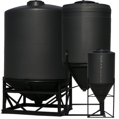
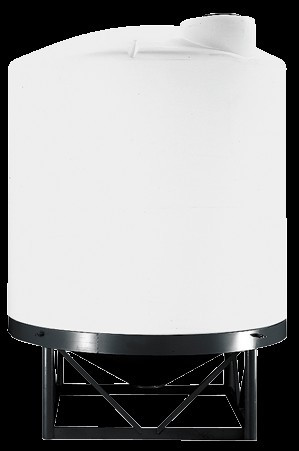
Tanks like the Norwesco N-43852 1,000 gallon 45-degree cone-bottom sidestep the residual-heel problem entirely by using a center-drain cone geometry, but they require a stand structure that the sloped-bottom configuration does not. The decision between sloped-bottom and cone-bottom is a stand-cost vs residual-heel trade.
3. Level Survey Methodology for As-Installed Acceptance
The level survey has to measure both the tank pad and the tank exterior reference points to separate the pad contribution from the molded geometry contribution. The standard procedure:
Step 1: Pad level survey. Use an optical level or a digital level with sub-degree accuracy. Set the instrument 10-20 feet from the tank pad on stable ground. Sight to four cardinal points on the top edge of the concrete or compacted aggregate pad: 0 degrees, 90 degrees, 180 degrees, 270 degrees relative to the planned outlet position (12 o'clock, 3 o'clock, 6 o'clock, 9 o'clock). Record elevations to the nearest 0.05 inch. Compute the maximum out-of-level: high point elevation minus low point elevation.
Step 2: Compute pad slope contribution. Pad out-of-level divided by pad diameter, expressed in degrees: arctan(delta_elevation / pad_diameter). A 0.5-inch out-of-level on a 96-inch pad gives arctan(0.5/96) = 0.30 degrees. That contribution adds to or subtracts from the molded slope depending on direction relative to the outlet.
Step 3: Tank exterior reference survey. With the tank installed and empty, sight to the molded tie-down lugs (or the top edge of the tank if no lugs) at the same four cardinal points. Record elevations. Subtract the pad elevations from the tank elevations to get the wall-height-above-pad at each point. Differences in wall-height-above-pad indicate that the tank itself is not seated flat on the pad, which can happen if the pad has high or low spots or if the tank rim is out of round.
Step 4: Verify slope direction. The molded slope should run from the upslope wall to the outlet wall along a single axis. Confirm by sighting along the floor line through the manway or by measuring the interior floor depth at the four cardinal points with a calibrated dipstick. The depth differential between the upslope and outlet sides should match the molded slope spec: 5 inches for 3 degrees, 8.4 inches for 5 degrees, 11.8 inches for 7 degrees on a 96-inch tank, plus or minus the pad contribution from Step 2.
Step 5: Document and accept or reject. Acceptance criterion is typically: as-installed effective slope within plus or minus 0.5 degrees of the specified slope, pad out-of-level under 0.5 degrees in any direction, slope direction within 5 degrees of the planned axis. Any failure triggers a pad correction or a tank reseat before the tank is filled.
4. Drain Protocol by Slope Angle
The drain protocol is the operational discipline that converts the molded slope into a repeatable evacuation outcome. The protocol differs by slope angle because the gravity drive on the residual liquid wedge differs.
3-degree drain protocol. Open the outlet valve fully. Allow gravity drain until visible flow at the outlet drops below a defined threshold (typically 1 gallon per minute). At that point, close the outlet, wait 15 minutes for surface tension drainage of the upslope wall to equalize the wedge, then open the outlet again. Repeat the wait-and-drain cycle until no measurable flow occurs in a 15-minute window. Final residual is the static wedge volume plus the dead heel below the outlet centerline. Total drain time on a 1,500-gallon 3-degree tank: typically 20-40 minutes.
5-degree drain protocol. Open the outlet valve fully. Single-pass drain is usually sufficient because the slope is steep enough to maintain consistent gravity flow until the wedge is reduced to the static residual. One wait-and-drain cycle of 5 minutes after first flow termination is good practice. Total drain time on a 1,500-gallon 5-degree tank: typically 12-25 minutes.
7-degree drain protocol. Open the outlet valve fully. Single-pass drain. The 7-degree slope drives essentially complete drainage to the static residual in one pass. No wait-and-drain cycle needed. Total drain time on a 1,500-gallon 7-degree tank: typically 8-15 minutes.
The protocol assumes a fully open outlet valve and unrestricted downstream piping. Any flow restriction (a partially closed valve, an undersized hose, a long horizontal run with friction loss) increases drain time and can interact with the slope geometry to leave more residual than the math predicts. Verify drain protocol by direct measurement of residual liquid depth at the upslope wall after a full drain cycle; document the result for change-over QA.
5. Sump and Pump-Out Strategies for Sloped-Bottom Tanks
If the operational requirement is full evacuation, not just gravity drain to residual heel, a sump or pump-out provision has to be added to the sloped-bottom geometry. Three patterns are common:
Sump-mounted bulkhead at the lowest point. A small recessed sump (typically 4-6 inches diameter, 2-4 inches deep) is molded or fabricated into the floor at the lowest point of the slope. The bulkhead outlet centerline is at the bottom of the sump, not the bottom of the slope. The sump traps the static residual wedge plus the wetted-wall film and provides a positive low point for last-gallon evacuation. Field implication: the sump becomes the solids accumulation point and requires periodic clean-out access via the manway.
Wand pump-out via manway. A flexible suction wand on a portable diaphragm or peristaltic pump enters through the manway and the operator sweeps the upslope wedge to lift the standing liquid. Procedural; works for any slope angle. Adds 15-30 minutes per drain cycle and requires safe entry discipline if the manway is more than minimally accessible.
Air-blow assist. A compressed-air injection at the top of the upslope wall pushes the residual wedge toward the outlet during the final drain phase. Effective only on chemistries where atomization is acceptable; not for hypochlorite, not for VOC service, not for any chemistry where vapor generation is a regulatory issue. Where applicable (water, dilute brine, slurries with non-volatile carriers), air-blow can reduce the residual wedge by 50-70 percent in 2-5 minutes of assist time.
For high-consequence chemical service where complete evacuation matters, the cone-bottom geometry is generally a better fit than sloped-bottom because the cone delivers center drainage without a wedge geometry. Cone-bottom tanks like the Norwesco N-43852 1,000 gallon 45-degree cone and the Norwesco N-42064 15-gallon 57-degree inductor achieve sub-1-percent residual heel without sump or pump-out hardware. The trade is the stand structure, the higher overall installed height, and the fall-protection considerations on elevated tanks.
6. Common Slope-Verification Findings and Corrective Actions
The most common failure modes from field-installed sloped-bottom tanks:
Pad out-of-level greater than 1 degree opposite the slope direction. This is the most common finding on first-time installations and the most damaging operationally because it directly subtracts from the effective slope. A 5-degree tank on a 1.5-degree adverse pad has effectively 3.5 degrees of slope, which leaves a deeper standing liquid wedge than the chemistry change-over protocol assumed. Corrective action: shim the tank tie-downs to bring the pad-effective surface back to true level, or grout the pad to correct the high-low pattern. Do not reduce drain protocol expectations to match the degraded slope; correct the pad.
Outlet at a height above the lowest floor point. Bulkhead installation tolerance allows the outlet to be 0.5 to 1.5 inches above the molded lowest floor point in some assemblies. The dead heel below the outlet plane is then the difference between molded low point and outlet centerline times the floor area at that elevation. Operationally, this dead heel is permanent and is added to the wedge residual. Corrective action: relocate the bulkhead to the molded low point if the manufacturer's reinforcement boss permits, or accept the dead heel and document it in the change-over protocol.
Tank rim out of round. Rotomolded tanks have an ovality tolerance per ASTM D1998 that allows up to 1 percent out-of-round at the top rim. On a 96-inch nominal-diameter tank, that is 0.96 inch of ovality. The ovality usually does not affect the floor geometry but can affect the apparent levelness if the level survey references the rim. Corrective action: reference the level survey to molded features on the lower hemisphere (tie-down lugs, pad-contact ring) rather than the rim.
Slope direction not aligned with outlet. The molded slope axis on a rotomolded tank is referenced to a feature on the mold parting line, and the bulkhead penetration is drilled at the field-installed orientation. If the operator orients the tank with the outlet 90 degrees off the slope axis, the actual drainage path is across the slope, not down it, and the effective slope at the outlet is zero. Corrective action: rotate the tank to align the outlet with the downslope side; verify by interior floor depth measurement at the outlet and at the diametrically opposite point.
7. Slope Selection Decision Framework by Service
The slope-angle selection should follow the service requirements, not default convention. The decision framework:
- Bulk water and dilute brine, no chemistry change-over: 3-degree slope acceptable. Residual heel is not operationally significant on water service. Lowest installed cost.
- Single-chemistry service, chemistry-specific tank: 3 to 5-degree slope. Residual heel is less critical because the next fill is the same chemistry. 5-degree gives faster drain.
- Multi-chemistry change-over service: 5 to 7-degree slope plus sump or pump-out. Residual heel between chemistries is a contamination risk; minimize it by combining steeper slope with positive sump evacuation.
- Solids-bearing or settling slurry service: 7-degree slope minimum, with bottom-side mixing if solids exceed 5 percent by weight. The steeper slope reduces solids accumulation on the upslope side.
- Hypochlorite, brine, or other corrosive chemistries with antioxidant package consumption concerns: 5-degree slope plus complete-evacuation pump-out. Residual liquid in the tank between fills accelerates oxidative degradation at the wetted-wall band.
- Pharmaceutical, food-grade, or NSF 61 service: 7-degree slope plus sump and pump-out, plus crowned-rim and full-floor cleanability. Residual is a sanitation defect.
The five-brand catalog covers the slope-angle range. Sloped-bottom Norwesco verticals are commonly specified at 5 degrees; sloped-bottom Snyder Captor and double-wall units run 5 to 7 degrees; Enduraplas industrial verticals like the EP-THV02500FG 2,500 gallon are typically flat-bottom on the standard line and require side-mounted pump-out for evacuation; Chem-Tainer offerings span the slope-angle range; Bushman is primarily flat-bottom for water service. For specifications matched to a particular drainage requirement, contact OneSource Plastics at 866-418-1777 with the chemistry, residual-heel target, and change-over cadence.
8. Documentation Package for As-Installed Slope Acceptance
The acceptance documentation that converts a field installation into a commissioned tank:
- Tank ID, manufacturer, SKU, slope spec from cut sheet.
- Pad level survey at four cardinal points, elevation values to 0.05 inch, computed pad slope and direction.
- Tank exterior level survey at four cardinal points referenced to molded features, computed wall-height-above-pad differential.
- Interior floor depth measurement at the four cardinal points, computed effective slope and direction.
- Outlet centerline elevation above the molded lowest floor point (the dead-heel offset).
- Drain test data: time to first flow termination, time to final flow termination, measured residual liquid depth at upslope wall after final drain cycle.
- Acceptance disposition: accepted, accepted with conditions (specify), rejected and corrected.
- Engineer or designated owner signature.
The documentation typically takes 2-3 hours to complete on a single tank and then becomes the baseline for ongoing operational assurance. Subsequent annual or change-over inspections compare back to the as-installed baseline; any drift in residual liquid depth or drain time indicates pad settlement, fitting issues, or chemistry-side accumulation that warrants investigation.
9. Brand-by-Brand Sloped-Bottom Default Configurations
- Norwesco vertical sloped-bottom: 5-degree slope to side outlet, common across the product line. Reference: N-40146 1,500 gallon, N-40164 5,000 gallon, N-43128 10,000 gallon.
- Snyder Captor double-wall sloped-bottom: 5-degree slope, integrated annular containment. Reference: SII-5490000N42 1,550 gallon, SII-5990102N42 1,000 gallon.
- Snyder waste oil double-wall: integrated drain pan geometry; reference 5-degree convention. Reference: SII-5740102N95703 275 gallon.
- Norwesco cone-bottom: 45-degree or 57-degree center-drain cone, sub-1-percent residual heel without pump-out. Reference: N-43852 1,000 gallon 45-degree, N-42064 15-gallon 57-degree inductor.
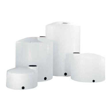
- Enduraplas industrial vertical: primarily flat-bottom; reference EP-THV02500FG 2,500 gallon. Side-mounted pump-out required for evacuation.
- Chem-Tainer vertical: sloped-bottom available; TC6446IA 500 gallon HDPE.
- Bushman water: flat-bottom default for stationary water reserve. Reference: BM-WW-1500-GL-NAT 1,500 gallon.
OneSource Plastics ships sloped-bottom and cone-bottom tanks with manufacturer cut sheets and the full slope-angle specification. List pricing by SKU is published on each product page; LTL freight to your ZIP is quoted separately via the freight estimator or by phone at 866-418-1777. For operations where residual heel has a defined chemistry-change-over impact, a slope-angle selection consultation matched to your change-over cadence is available.
For complementary reading, see our cone-bottom vs flat-bottom decision article for the parallel discussion on cone geometry, and our drainage residual-heel by tank shape for the comparative-geometry numbers.
Recommended Tanks for This Guide
Live pricing, updated automatically · estimate freight to your ZIP.