Tank Site Drainage Engineering: Subgrade Slope Design for Rainwater Tanks and Septic


The single most ignored parameter in plastic-tank installation is the rainfall load that hits the pad and the rainfall load that the tank itself sheds. Buyers spec 1500-gallon tanks to the inch on diameter, then drop them on a flat patch of compacted gravel that drains to the foundation of a building. Within two seasons the pad has migrated, the tank is leaning, the bulkhead is weeping, and the warranty conversation begins. The fix is not bigger gravel. The fix is a drainage profile engineered with the same care that the tank itself was engineered for.
This guide walks the rainwater drainage and septic drainage problems separately and then together, because most real installs are doing both — a vertical poly tank collecting roof runoff sitting 60 feet from a septic mound, all of it draining to the same surface watershed. We cite ASTM, EPA SPCC, ASCE 7, NRCS, and state on-site sewage program rules. No fabrication.
Two Problems in One Yard
Rainwater capture and septic systems share a watershed but have opposite drainage requirements. The rainwater tank must shed every drop that hits it AWAY from the foundation pad — settled water under the pad migrates fines and produces non-uniform support. The septic drainfield must accept percolating effluent through engineered subgrade and dispose of it via soil microbial action — water arriving from above (storm runoff) saturates the field and produces hydraulic overload, biomat failure, and surface seepage.
The rule of thumb most installers learn first: rainwater tank pad slopes AWAY from the building and AWAY from the drainfield. The drainfield receives ZERO surface runoff — it is upgradient or laterally diverted from the tank pad. Get this wrong and you have created a soakaway under your tank that simultaneously floods your drainfield. In wet seasons that combination has produced foundation cracking, tank settling, and septic surfacing inside 18 months.
Subgrade Engineering for Plastic Tanks
ASTM D1998 governs polyethylene upright storage tanks but does not specify pad design. The tank manufacturers do — Norwesco, Snyder, Chem-Tainer, Bushman, and Enduraplas all publish pad requirements. The recurring requirements:
- Flat across the tank footprint: deviation under 0.25 inch in 4 feet (less than 1/16 inch per foot) measured with a 4-foot straightedge in any direction. Tanks settle into uneven pads and bulkhead fittings carry the bending stress.
- 6-inch minimum compacted aggregate base (3/4-inch crushed angular stone) on undisturbed subgrade or 95%-compacted granular fill per ASTM D698 (Standard Proctor) or ASTM D1557 (Modified Proctor) depending on tank size.
- Pad extends a minimum of 12 inches beyond tank diameter on all sides. Many manufacturers require 18-24 inches on tanks 1,500 gallons and up.
- Drainage off the pad in all directions at minimum 2% slope (1/4 inch per foot) for the 6 feet immediately surrounding the tank.
- No standing water within the perimeter pad at any time including 100-year storm event.
The 2% perimeter slope is the parameter installers cut corners on. They build flat pads because flat is easier. Within one wet season, the pad puddles, fines wash, the aggregate compacts non-uniformly, and the tank tilts.
Why Slope Matters Mechanically
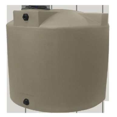
A 1500-gallon vertical tank like the Norwesco MPN 41504 (1500 gallon natural-white vertical, 64-inch diameter, 116-inch tall, listed at $1,389.00) weighs roughly 250 lb empty and 12,750 lb full of water. That load is distributed across a 22.5-square-foot circular footprint — about 567 lb per square foot static. Add wind load (ASCE 7-22 Chapter 26 calculates ~25 psf at 90 mph 3-second gust over 30 ft height) and seismic moment (ASCE 7-22 Section 15 for non-building structures), and the moment at the base of the tank during a storm event easily reaches 18,000 ft-lb of overturning.
If your pad has a 0.5-inch dip on one side and water has been collecting there for six months, the aggregate has migrated, the support is non-uniform, and that overturning moment is now resisted by 20% less effective contact area. The math is unforgiving. Get the slope right or the wind WILL find your tank.
Pad Materials by Tank Size
| Tank capacity | Aggregate base | Concrete pad option | Pad extension |
|---|---|---|---|
| Under 500 gal | 4-inch compacted #57 stone | Optional 4-inch slab | 12-inch perimeter |
| 500 - 1,500 gal | 6-inch compacted 3/4-inch crushed | 4-inch slab with #4 mesh, 3,500 psi | 18-inch perimeter |
| 1,500 - 3,000 gal | 8-inch compacted with geotextile separator | 6-inch slab with #4 reinforcement | 24-inch perimeter |
| 3,000+ gal | Engineered base, soils report recommended | Engineered slab, frost-depth footing | 30+ inch perimeter |
For a 3000-gallon Snyder Industries vertical (representative MPN class WB46/WB47 1500-gallon at $1,540 list, scaling up to 3000-gallon class), the engineered pad spec is non-negotiable in seismic Site Class D or higher and in frost-depth jurisdictions.
Rainwater Tank Drainage: Roof to Tank to Overflow
A roof-fed rainwater capture tank must shed three sources of water reliably: roof runoff INTO the tank, condensation/precipitation OUTSIDE the tank, and overflow OUT of the tank when full. Each path has independent failure modes.
Roof Inlet Sizing
Per the International Plumbing Code Section 1108 (rainfall design), inlet downspout sizing assumes 100-year 1-hour rainfall intensity per ASCE 7-22 or NOAA Atlas 14. A 2,000 sq ft roof in coastal North Carolina (8.5 inch/hour 100-year storm per NOAA Atlas 14 NC Coastal Zone) sheds 1,063 gallons per minute at peak. A single 4-inch downspout passes about 130 GPM at the standard 1/8-inch slope per foot — so the roof needs four downspouts plus tank inlet capacity to match. Tank inlets sized too small back up roof gutters and produce overflow at the roof line, which is exactly what you are trying to avoid.
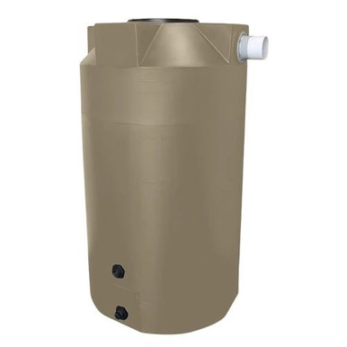
The Bushman MPN 45444 (730 gallon low-profile vertical rainwater collection tank in mocha, listed at $1,199.99) is purpose-engineered for residential-scale rainwater capture with appropriate inlet geometry. For larger systems, the Bushman MPN WW-1500-GL-NAT (1500-gallon water storage tank, listed at $1,699.99) accepts higher inlet flow rates.
First-Flush Diverter
The first 0.04 inch of rainfall off a roof carries 80%+ of the bird droppings, leaf debris, asphalt particles, and atmospheric deposition. A first-flush diverter sized at minimum 10 gallons per 1,000 sq ft roof (per Texas Manual on Rainwater Harvesting Section 2 published by Texas Water Development Board) routes this initial flow to a separate small tank or drains it to landscape. The remaining roof runoff enters the storage tank.
Without a first-flush diverter, biofilm grows in the storage tank within months, even on potable-rated NSF/ANSI 61 polyethylene. The diverter is a $40 fitting. Skip it and pay $400 in tank cleaning, or worse, contaminate downstream uses.
Tank Overflow Geometry
Tank overflow must discharge at minimum 5 feet from the foundation of the building and AWAY from the drainfield. The overflow line is sized to pass 100% of the inlet rate, not the average — when the tank is full and the storm is at peak, the overflow IS the inlet pipe in capacity terms. A 4-inch inlet must have a 4-inch overflow, period.
Discharge to a rock-lined splash pad of 36-inch diameter minimum, sloped 4% AWAY from foundation. The Norwesco MPN 41464 (100 gallon vertical black, $393.86 list) sample tank documentation calls out 2-inch overflow as standard; for tanks 500 gallon and up, 3-inch and 4-inch overflows are standard from Norwesco, Snyder, and Bushman.
Septic Drainage: The Drainfield as Engineered Infrastructure
The drainfield is not a hole in the ground. It is engineered hydraulic infrastructure, sized by percolation rate (perc test, ASTM D5126 or state-equivalent), bedded in graded aggregate, and protected from surface water intrusion. Its design loading is based on EPA Onsite Wastewater Treatment Systems Manual EPA/625/R-00/008, state on-site sewage program rules, and local soil report.
Slope Diversion Above the Drainfield
A drainfield sited downslope of a roof, driveway, or rainwater tank pad is hydraulically overloaded by every storm. The diversion swale upgradient of the drainfield must intercept ALL surface runoff from the contributing watershed. State on-site sewage rules typically require:
- Diversion swale upgradient of drainfield, minimum 1% slope, sized for 25-year 24-hour storm event per NRCS Conservation Practice Standard 410 (Grassed Waterway).
- 10-foot minimum buffer between any aboveground tank pad runoff and drainfield (varies by state — Texas 30 TAC Chapter 285 specifies 10 feet drainfield to property line, 50 feet to wells; California Onsite Wastewater Treatment Systems Policy specifies similar; verify local rule).
- No vehicular traffic over drainfield at any time. The aggregate base compacts and the soil pore structure collapses, eliminating the percolation function.
- Surface vegetation on drainfield to be shallow-rooted grass; no trees, no impermeable hardscape.
Tank-Pad-to-Drainfield Layout Geometry
For a typical residential install with rainwater capture and septic on the same lot:
- House (highest grade): roof drains to gutters to downspouts to first-flush diverter to rainwater tank.
- Rainwater tank (mid-grade): sited downslope of house, upslope of drainfield. Pad slopes 2% in all directions OUTWARD. Overflow piped at minimum 4-inch to discharge swale that empties to vegetated swale or stormwater system.
- Drainfield (lowest grade): sited downslope of all other infrastructure with intact diversion swale upgradient. No surface flow enters the drainfield from any direction.
- Septic tank: sited between house plumbing and drainfield, on its own pad, with watertight inspection ports and effluent filter.
This layout is not optional in jurisdictions that enforce on-site sewage rules. New York 10 NYCRR Appendix 75-A, Pennsylvania 25 Pa. Code Chapter 73, Tennessee TDEC Rule 0400-48-01, Florida FS Section 381.0065 — all carry diversion-swale-around-drainfield language. Verify your state's rule via the appropriate program (we cite state-specific rules in our State Septic Tank Regulations hub for 50 states).
Storm Event Sizing: ASCE 7 and NOAA Atlas 14
Pad drainage and overflow capacity are sized to the design storm. Two governing standards:
- ASCE 7-22 Section 8 — Rain Loads. Specifies rainfall intensity for rooftop drainage; references local code-adopted return-period storm.
- NOAA Atlas 14 — Precipitation-Frequency Atlas of the United States. Source data for return-period rainfall by ZIP code. Available at hdsc.nws.noaa.gov for any U.S. coordinate.
For most residential rainwater capture, design to the 25-year 1-hour rainfall intensity. For commercial systems, design to 100-year. For critical-use systems (fire suppression reserve, emergency potable storage), design to the 100-year 24-hour event volumes plus 25% factor of safety.
Worked Example — North Carolina Coastal
Site: Wilmington NC. Roof: 2,400 sq ft. Rainwater tank: 1,500-gallon Norwesco MPN 41504 ($1,389.00 list).
- NOAA Atlas 14 NC Coastal — 25-year 1-hour rainfall: 4.7 inches/hour
- Roof catch: 2,400 sq ft × 4.7 in/hr × 0.62 gallons/sq ft/in = 6,994 gallons in the design hour
- Tank fills in approximately 13 minutes at peak. Overflow MUST handle the rest.
- Required overflow capacity: roof shed rate minus tank fill rate ≈ 530 GPM continuous
- Pipe sizing per Manning's equation, n=0.013 PVC, 1% slope: 4-inch handles 250 GPM, 6-inch handles 700 GPM. Spec 6-inch overflow.
This is the math that determines whether your overflow handles the storm or backs up into your soffits. Do not specify a 4-inch overflow on a 6,000-GPM-design-hour roof. Run the numbers.
EPA SPCC and Stormwater Implications for Larger Sites
For commercial and agricultural sites with aggregate aboveground oil storage exceeding 1,320 gallons (excluding containers under 55 gallons), EPA Spill Prevention, Control, and Countermeasure (SPCC) rule applies — 40 CFR Part 112. SPCC requires:
- Secondary containment sized to 110% of largest tank for general industry (40 CFR 112.7(c)) or 100% plus precipitation for outdoor uncovered installations
- Stormwater management in the containment area to discharge clean rainwater while retaining any oil release
- Drainage valve on containment, normally closed, with documented inspection-and-discharge protocol per 40 CFR 112.8(c)(3)
For oil storage subject to SPCC, the containment area drainage is the EPA-regulated path. See our pillar guide for 110% vs 125% Secondary Containment Math for the volume sizing decision tree.
Common Drainage Failure Modes
Failure 1 — Pad with no slope
Tank settles into puddle that forms after every rain. Within 12-24 months, foundation pad migrates and fittings stress. Resolution: rebuild pad with proper slope.
Failure 2 — Overflow undersized
2-inch overflow on 1,500-gallon tank fed by 1,800-sq-ft roof. Storm event backs water into roof gutters and over fascia. Resolution: replace overflow with 4-inch or 6-inch, route to splash pad or vegetated swale.
Failure 3 — Drainfield downslope of impervious surface
Driveway, hardscape, or large roof shedding directly onto drainfield. Drainfield biomat fails within 1-3 years; effluent surfaces. Resolution: install diversion swale or French drain interceptor upgradient.
Failure 4 — Rainwater tank overflow daylighting at foundation
Overflow line discharges 3 feet from house. Foundation gets soaked every storm. Long-term: foundation cracking, basement seepage, mold. Resolution: extend overflow at least 10 feet from foundation, slope at 4% to splash pad.
Failure 5 — Pad gravel without geotextile separator
Aggregate base migrates into native soil through traffic + freeze-thaw. Pad height drops, slope flattens, drainage fails. Resolution: lift tank, install non-woven geotextile (4-oz minimum), rebuild aggregate base.
Failure 6 — Frost-depth pad failure
Pad poured above frost depth in zones that freeze. Frost heave lifts pad non-uniformly each winter; over 5-10 cycles the tank tips. Resolution: extend pad to local frost depth (typically 36-48 inches in northern states; verify with local building department).
Specifying the Site Right the First Time
The drainage decisions above are made at site survey, not at install. The order of operations:
- Determine roof catchment area and design storm via NOAA Atlas 14.
- Size tank for use case (capacity coverage) using our Tank Sizing Calculator — capacity sizing is independent of drainage sizing but informs pad load.
- Run a perc test or pull the soils report. Determine subgrade bearing capacity and frost depth.
- Lay out site with house at top of grade, tank mid-grade with 2% slope away from foundation, drainfield at lowest grade with diversion swale.
- Spec pad per tank size table above, with appropriate aggregate base depth and perimeter extension.
- Spec overflow per Manning's equation for design storm rate.
- Verify state on-site sewage rule for setbacks (drainfield to property line, well, water body).
- Submit site plan to local permit authority before excavation.
Internal Resources
- Tank Foundation Pad Engineering
- Secondary Containment Volume Math (EPA SPCC)
- Aboveground vs Belowground Storage Engineering
- Rainwater Harvesting Tank Sizing by State
- State Septic Tank Regulations
- Tank Sizing Calculator
- Freight Cost Estimator
- Contact OneSource
Source Citations
- ASTM D1998 — Standard Specification for Polyethylene Upright Storage Tanks
- ASTM D698 — Standard Test Methods for Laboratory Compaction Characteristics of Soil Using Standard Effort
- ASTM D1557 — Standard Test Methods for Laboratory Compaction Characteristics of Soil Using Modified Effort
- ASTM D5126 — Standard Guide for Comparison of Field Methods for Determining Hydraulic Conductivity in Vadose Zone
- ASCE 7-22 — Minimum Design Loads and Associated Criteria for Buildings and Other Structures (Sections 8 Rain Loads, 15 Non-Building Structures, 26 Wind Loads)
- NOAA Atlas 14 — Precipitation-Frequency Atlas of the United States, hdsc.nws.noaa.gov
- EPA Onsite Wastewater Treatment Systems Manual — EPA/625/R-00/008
- EPA Spill Prevention, Control, and Countermeasure Rule — 40 CFR Part 112
- NRCS Conservation Practice Standard 410 — Grassed Waterway
- International Plumbing Code Section 1108 — Storm Drainage Design
- NSF/ANSI 61 — Drinking Water System Components, Health Effects
- Texas 30 TAC Chapter 285 — On-Site Sewage Facilities
- California Onsite Wastewater Treatment Systems Policy (SWRCB)
- New York 10 NYCRR Appendix 75-A — Standards for Individual Onsite Wastewater Treatment Systems
- Pennsylvania 25 Pa. Code Chapter 73 — Standards for Onlot Sewage Treatment Facilities
- Tennessee TDEC Rule 0400-48-01 — Subsurface Sewage Disposal Systems
- Florida FS Section 381.0065 — Onsite Sewage Treatment and Disposal Systems
- Texas Manual on Rainwater Harvesting — Texas Water Development Board, 3rd Edition
- OneSource Plastics master catalog data — 9,419 products, 2026-03-26 snapshot
Recommended Tanks for This Guide
Live pricing, updated automatically · estimate freight to your ZIP.