Fill-Pipe Terminal Velocity Engineering for Solid-Bottom Polyethylene Tanks: Drop-Tube Distance from Floor, Splash and Foam Suppression, Static-Charge Generation Limits, and Why API 2003 One-Foot Rule Maps Directly to Plastic AST Service


The fill pipe is the entry path for product into the tank. It is also the most concentrated point of energy delivery anywhere on the tank, and the engineering decisions on how that fill pipe terminates inside the tank determine three independent failure modes: splash and foaming during fill, static charge generation in flammable service, and direct erosion damage to the tank floor at the impingement zone. The petroleum industry codified the answer in API 2003 (Protection Against Ignitions Arising Out of Static, Lightning, and Stray Currents) decades ago: terminate the fill pipe within one foot of the tank bottom, with the discharge directed downward or sideways but not upward, and limit the fill velocity to under 1 meter per second during the splash-loading window. The petroleum-industry rule maps directly to plastic AST service for water, chemicals, and any product where the entry energy can damage the tank or generate hazardous foam. This guide walks the engineering of fill-pipe termination on solid-bottom polyethylene tanks.
Reference standards cited: API 2003 Protection Against Ignitions Arising out of Static, Lightning, and Stray Currents, 8th Edition; NFPA 77 Recommended Practice on Static Electricity, 2024 Edition; NFPA 30 Flammable and Combustible Liquids Code; IEC 60079-32-1 Explosive Atmospheres - Electrostatic Hazards; manufacturer fill-pipe drop-tube specifications from major OEMs including Norwesco, Snyder, and Enduraplas.
1. The Three Failure Modes from Above-Floor Fill Termination
A fill pipe that terminates more than one foot above the tank floor produces three concurrent failure modes during the fill cycle:
Splash and aeration: the falling stream of incoming product impacts either the tank floor or the existing liquid surface, generating turbulence that entrains air, creates foam, and aerosolizes droplets. For water and aqueous chemicals, the foam typically dissipates within minutes. For petroleum products, the aerosol enters the headspace and creates a flammable vapor cloud at higher concentrations than the product would otherwise produce. For viscous chemicals (concentrated polymers, surfactants), the foam can persist for hours and cause vent blockage.
Static charge generation: turbulent flow through the fill pipe and impingement against the floor or surface separates electrons from the product molecules, leaving the bulk liquid electrostatically charged. NFPA 77 documents that splash filling generates 10-100 times the static charge of submerged filling. In flammable service, the charge accumulates on the liquid surface until it discharges to a grounded conductor (a tank wall, a dipstick, an overfill protection probe), and the discharge spark ignites the headspace vapor. This ignition mechanism is responsible for the documented petroleum tank fires that occur during fill operations despite proper grounding of the tank itself - the static is generated inside the tank during fill, not externally.
Floor impingement damage: the falling stream impacts the floor at the terminal velocity of the falling jet plus any pump-imposed velocity. For a fill pipe terminating 36 inches above a tank floor with product flowing at 100 GPM through a 2-inch pipe, the impingement velocity at the floor is approximately 8-10 feet per second. Sustained impingement at that velocity erodes the polyethylene surface over time, producing a thinned region directly under the fill pipe that becomes the failure point. Documented tank failures from this mechanism are rare but occur on tanks in continuous fill service; the mechanism is the same one that erodes river beds at waterfall plunge pools.
2. The API 2003 One-Foot Rule
API 2003 Section 4.2 establishes the recommended practice for splash-loading mitigation in petroleum tanks: terminate the fill pipe within one foot of the tank bottom. The technical justification has three components.
First, the fill pipe terminating below the existing liquid level submerges the discharge, eliminating the falling-jet impingement against the surface and the associated splash, aeration, and static-charge generation. Submerged-fill operations produce static-charge densities approximately 10x lower than splash-fill, falling within the safe limit for normal fill-velocity operations.
Second, the residual liquid heel that always exists at the bottom of an operating tank (the volume below the lowest pump-out fitting) is sufficient depth to submerge a fill pipe terminating 12 inches above the floor for the bulk of the fill cycle. The first 30-60 seconds of a fill cycle on a fully-drained tank may be above the heel, but the splash-loading exposure window is bounded.
Third, the one-foot termination height places the discharge in a region of low floor-impingement risk. The falling-jet velocity from a 12-inch drop is approximately 2.8 feet per second from gravity alone (sqrt(2*32.2*1) = 8 ft/s, but the kinetic energy spreads in the radial direction at the floor, so the impingement velocity is less than the free-fall terminal velocity). This is below the erosion threshold for polyethylene under sustained low-velocity contact.
The rule maps directly from petroleum to non-petroleum service. Water, sodium hypochlorite, sulfuric acid, sodium hydroxide, polymer solutions, and any other product in plastic AST service all benefit from the same termination height. The rule should be considered the default specification regardless of product chemistry.
3. Drop-Tube Hardware: What It Is, How It Works
The hardware implementation of the API 2003 rule is the drop tube: a length of pipe extending from the fill nozzle on the tank dome down through the headspace and terminating 12 inches above the floor. Drop tubes are standard fittings available from all major polyethylene tank manufacturers and from specialty fitting houses (Banjo, OPW, Husky).
The drop tube specification:
- Diameter matched to fill nozzle: 2-inch fill nozzle takes a 2-inch drop tube. Reducing the diameter through the drop tube increases velocity and re-creates the splash-loading exposure that the drop tube was meant to eliminate.
- Length specified to the tank height: drop tube must terminate 12 inches above the floor at the bottom of the tank. For a 1,500-gallon vertical Norwesco N-40146 with internal height of approximately 89 inches and dome height adding 6-8 inches, the drop tube length is approximately 77-79 inches.
- Material compatible with chemistry: PVC drop tubes for general service, CPVC for hot caustic, stainless 316L for petroleum or aggressive chemistry, PVDF for highly corrosive. Match the drop tube material to the service.
- Termination geometry: straight-cut termination (most common, simplest), 45-degree angle cut (directs flow against the wall to dissipate energy), or splash-deflector cup (eliminates floor-impingement entirely by spreading the flow over a flat plate). Angle-cut and deflector-cup are more expensive but worth specifying for tanks with high-cycle fill operations or for chemistry where floor erosion is a concern.
- Top-end attachment: threaded into the bottom of the fill nozzle, or flanged to the underside of the dome with bolts. Threaded is simpler; flanged is more secure for tanks with frequent removal for cleaning.
The catalog tanks ship with the dome fill nozzle as a flush 2-inch threaded coupling. The drop tube is an after-market addition specified at order entry or installed in the field. Typical added cost is 75-200 dollars for the tube and brackets, plus 30-60 minutes of installation labor.
4. Fill Velocity Limits and the One-Meter-Per-Second Window
NFPA 77 Section 16 and API 2003 both reference a fill velocity threshold of approximately 1 meter per second (about 3.3 feet per second) during the splash-loading window when the fill pipe is not yet submerged. The threshold is calibrated to the static-charge generation rate above which spark-ignition becomes plausible in flammable headspace conditions.
For water, mild chemicals, and other non-flammable service, the 1 m/s rule is not a hard safety limit, but it is still good practice. Higher fill velocities through a non-submerged fill pipe produce more aeration, more foam, and more aerosol generation, all of which reduce fill efficiency and create operational nuisance. The petroleum-industry rule is a useful default for any service.
The fill-velocity calculation: V = Q / A, where Q is the volumetric flow rate and A is the pipe cross-section area. For a 2-inch pipe (cross-section area 0.0218 square feet), 1 m/s velocity equals 0.0218 * 3.28 * 60 * 7.48 = 32 GPM. For a 3-inch pipe, the equivalent velocity threshold is 73 GPM. For a 4-inch pipe, 130 GPM.
This sets the operational rule: during the first portion of a fill cycle on an empty or near-empty tank, throttle the fill pump to keep the fill-pipe velocity under 32 GPM (for 2-inch pipe) or 73 GPM (for 3-inch). Once the liquid level rises above the drop-tube termination - typically within the first 1-2 minutes of the fill cycle - the fill velocity can be increased to the design rate because the discharge is now submerged.
Modern fill controls implement this with a low-flow start sequence: pump runs at 30 percent capacity for the first 60-90 seconds, then ramps to full flow once a level transmitter confirms submergence. Manual implementation requires the operator to hold the pump throttle for the splash-loading window. Either approach works; the absence of any flow control during the splash-loading window is the failure pattern.
5. Aboveground Tank Fill Connections and Overfill Prevention
The fill connection at the tank dome is itself an engineering interface between the supply truck or pump and the drop tube. Standard configurations:
- Threaded male NPT cam-lock fitting: the most common for chemical-service AST. Camlock allows quick connection from a delivery hose. Specify the camlock material to be compatible with the chemistry; brass camlocks fail in chlorinated service.
- Tight-fill connector with vapor recovery: required for petroleum products under EPA Stage I vapor recovery in some jurisdictions. The tight-fill connector mates with the truck delivery hose to capture displaced vapors back to the truck. Reference EPA 40 CFR 60 Subpart XX.
- Overfill prevention valve: an automatic shutoff that closes the fill line when the tank level reaches a preset percent (typically 90-95 percent of capacity). Required for UST under 40 CFR 280.30; recommended for AST in chemical service. The OPV mounts at the dome above the drop tube.
- High-level alarm float: a level switch in the tank headspace that triggers an audible alarm at 80-85 percent of capacity, giving the delivery operator advance warning before the OPV closes. Required by some state UST programs; voluntary for AST.
The integration of these components matters for the fill-velocity and drop-tube design. The OPV must be sized so that the cracking velocity (the velocity at which the float lifts and closes the line) is well below the drop-tube design velocity, otherwise the OPV throttles flow during the splash-loading window and produces the very static-charge condition the drop tube was specified to prevent.
6. Tank Geometry and Drop-Tube Layout
The drop tube layout depends on tank geometry:
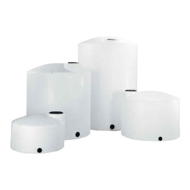
Vertical cylindrical tanks (the standard SKU): drop tube vertical from dome to within 12 inches of the floor. Centered drop tube is usual; offset drop tube can be specified for tanks where the dome fill port is offset from center. Length is approximately equal to the cylinder height minus 12 inches, plus dome height to the fill port.
Horizontal cylindrical tanks: drop tube terminates within 12 inches of the lowest interior point of the cylinder, which is at the centerline of the bottom rather than at the dished end. The drop tube length equals the depth from the fill port through the dome to the cylinder centerline, less the 12-inch standoff.
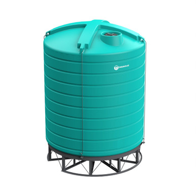
Cone-bottom tanks: drop tube terminates approximately 6 inches above the cone discharge point (the lowest internal surface), which is the ideal mixing point because the falling product helps suspend any settled solids and supports complete drainage during the next discharge cycle.
Sloped-bottom tanks (Snyder Captor): drop tube terminates 12 inches above the lowest point of the slope, which is the discharge fitting. Captor geometry directs the drop-tube discharge toward the outlet, which supports complete evacuation.
For all geometries, the drop tube must be securely fixed to prevent vibration during fill cycles. A loose drop tube oscillates against the tank wall and produces fatigue cracking at the dome attachment point over a 5-10 year service life. Specify stainless brackets at the dome and a plastic or stainless guide bracket at the drop tube terminus.
The Snyder SII-5490000N42 1,550 gallon double-wall ships with a sloped bottom that integrates with the drop-tube layout out of the box. The Norwesco N-40146 1,500 gallon vertical has a flat bottom that requires drop-tube specification at order entry; standard configuration ships without drop tube. The Norwesco N-43128 10,000 gallon vertical with high fill rates particularly benefits from drop-tube specification because the splash-loading exposure scales with tank size.
7. Failure-Mode Documentation
The patterns documented in fill-related plastic-tank incidents:
- Polymer foam dome compression: high-flow fill of polymer or surfactant solution into a tank without drop tube generates dense foam that fills the headspace. The foam blocks the atmospheric vent. Continued filling pressurizes the tank above its design pressure (atmospheric tanks are rated typically for 0.5 psig). Tank wall yields. Documented incidents on flocculant solution tanks at municipal wastewater plants. Mitigation: drop tube plus low-velocity start.
- Sodium hypochlorite splash decomposition: high-velocity splash of sodium hypochlorite into a tank generates micro-aerosol. The aerosol degrades faster than the bulk liquid and releases chlorine gas to the headspace. Continued filling creates a chlorine-saturated headspace. Operator opening the tank for inspection inhales chlorine. Mitigation: drop tube plus submerged fill.
- Diesel fill spark ignition: high-velocity splash filling of diesel into a previously-emptied tank generates static charge density above the spark threshold. Spark ignites residual vapor in headspace. Tank fire. Documented in petroleum bulk-plant operations. Mitigation: drop tube plus 1 m/s velocity limit during splash-loading window plus tank grounding plus bonding cable from delivery truck to tank.
- Floor impingement erosion: 4-inch fill pipe at high flow into a 2,500-gallon vertical tank without drop tube. After 8-12 years of service, the tank floor under the fill point is thinned by approximately 30-50 percent of original wall thickness. Floor failure during a routine fill. Mitigation: drop tube to spread the impingement zone and reduce velocity.
8. Specification Checklist for the Fill-Pipe Termination
- Confirm tank service is compatible with drop-tube material; specify body material accordingly.
- Specify drop tube length to terminate within 12 inches of the tank floor (or 6 inches above cone discharge for cone-bottom tanks).
- Specify drop tube diameter equal to fill nozzle diameter.
- Specify termination geometry (straight, 45-degree angle, or splash-deflector cup) per service.
- Specify dome attachment (threaded or flanged) per anticipated removal frequency.
- Specify guide bracket at drop-tube terminus to prevent vibration.
- For flammable service, specify low-flow fill control or operator-managed throttle for the splash-loading window.
- For overfill protection, specify OPV with cracking velocity above drop-tube design velocity.
- Document the fill-pipe specification on the tank installation drawing.
- Verify drop-tube placement at receiving inspection before placing the tank in service.
9. Brand-by-Brand Notes for Drop-Tube Configurations
- Norwesco vertical tanks: drop tube as factory option on tanks 1,000 gallons and larger. PVC, CPVC, or stainless options. Reference: N-40146 1,500 gallon, N-40635 3,000 gallon.
- Snyder Captor double-wall: drop tube with sloped-bottom integration available on chemical-service SKUs. Reference: SII-5490000N42 1,550 gallon, SII-5990102N42 1,000 gallon.
- Enduraplas vertical tanks: drop tube available as factory option; specify length and material at quote. Reference: EP-THV02500FG 2,500 gallon.
- Chem-Tainer vertical tanks: drop tubes available; specify body material and termination geometry at quote.
- Bushman vertical tanks: standard drop-tube package with PP body and stainless brackets available.
OneSource Plastics quotes complete fill-system packages including drop tube, OPV, high-level alarm, and tight-fill connector for petroleum or chemical service. List pricing on a 1,500-gallon vertical with full fill-system package starts at $2,650, with petroleum-rated configurations adding 200-500 dollars depending on overfill-prevention level. LTL freight to your ZIP is quoted via the freight estimator or by phone at 866-418-1777.
For complementary reading on related topics, see our tank static electricity prevention guide for the complementary grounding-and-bonding discussion, and our API 2000 vent sizing worked examples for the matching vent-side capacity calculation that goes hand-in-hand with fill-pipe sizing.
Recommended Tanks for This Guide
Live pricing, updated automatically · estimate freight to your ZIP.