Building Ventilation Rate Engineering for Indoor Tank Fill Operations: Vapor Displacement Math, ACGIH Threshold Limit Values as Design Targets, Local Exhaust vs Dilution Ventilation, and the ASHRAE 62.1 Floor That Indoor Tank Rooms Cannot Fall Below


An indoor or partially-enclosed tank fill operation displaces a volume of vapor-laden air every time the tank is topped up. The mass of vapor displaced depends on the chemistry, the chemistry temperature, the headspace concentration, and the fill rate. The fate of that displaced vapor — whether it dilutes into a building's general ventilation, accumulates in poorly-ventilated dead zones, vents to atmosphere through a properly-sized exhaust, or builds toward an explosive lower flammable limit — is what determines whether the operation is occupationally safe and whether it complies with the relevant codes.
This article walks the engineering basis for ventilation rate design on indoor tank-fill operations. The disciplines covered: vapor displacement math during fill, the ACGIH TLV and OSHA PEL framework as design targets, dilution ventilation calculations from the ACGIH Industrial Ventilation Manual, local exhaust ventilation at the fill point, the ASHRAE 62.1 floor that any occupied space must meet, NFPA 30 and NFPA 91 ventilation requirements for flammable and combustible service, and the sensor-and-control architecture that detects ventilation failures before they become occupational exposures or fire-and-explosion incidents. References cited are ACGIH Industrial Ventilation: A Manual of Recommended Practice (current edition), ASHRAE 62.1 (Ventilation for Acceptable Indoor Air Quality), NFPA 30 (Flammable and Combustible Liquids Code), NFPA 91 (Standard for Exhaust Systems for Air Conveying of Vapors, Gases, Mists, and Particulate Solids), OSHA 29 CFR 1910.1000 (toxic and hazardous substances; PELs), and ACGIH TLVs and BEIs (annual update; threshold limit values).
1. Vapor Displacement Math During Tank Fill
When a tank is filled, the volume of liquid added displaces an equal volume of vapor-laden headspace through the vent. The displaced vapor mass is the volume displaced times the headspace vapor concentration. For chemistries with measurable vapor pressure at storage temperature, the headspace is at or near saturation: the vapor concentration in the displaced air equals the chemistry's saturation vapor pressure divided by atmospheric pressure, multiplied by the molecular weight of the vapor.
For sodium hypochlorite at 12.5 percent at 70 degrees F: chlorine partial pressure approximately 12 mm Hg, atmospheric pressure 760 mm Hg, mole fraction 0.0158, mass concentration approximately 56 mg per liter of displaced headspace at saturation. A 1,500-gallon tank fill displaces 1,500 gallons or roughly 5,680 liters of headspace; total chlorine vapor mass displaced at saturation is approximately 318 grams. Filled at 50 GPM, the displacement rate is roughly 30 grams of chlorine vapor per minute.
For sulfuric acid 93 percent at 70 degrees F: sulfuric vapor pressure is essentially zero at ambient temperature; vapor displacement is negligible. The fill operation displaces air with trivial sulfuric content. Acid mist may be generated by splash and turbulence at the fill point, which is a separate engineering concern.
For 50 percent sodium hydroxide at 70 degrees F: sodium hydroxide vapor pressure is essentially zero; vapor displacement is air with negligible chemistry content. Aerosol from splashing is the practical exposure concern.
For ammonia 30 percent aqueous at 70 degrees F: ammonia partial pressure approximately 200 mm Hg, mole fraction 0.26, mass concentration roughly 180 mg per liter. A 1,500-gallon fill displaces roughly 1,000 grams of ammonia at saturation, far higher than the chlorine case. Aqueous ammonia fills are a primary indoor-ventilation engineering concern.
The displacement-rate calculation is the starting point for any ventilation engineering. Without it, ventilation sizing is a guess.
2. ACGIH TLV and OSHA PEL as Design Targets
The ventilation rate must dilute the displaced vapor below the relevant occupational exposure limit at the breathing zone of any worker present during fill. Two reference standards govern:
- OSHA Permissible Exposure Limits (PELs): 29 CFR 1910.1000 Table Z. Legally enforceable in U.S. workplaces. Generally derived from 1968 ACGIH values and not updated since the 1989 air contaminants rule was vacated.
- ACGIH Threshold Limit Values (TLVs): updated annually by ACGIH. Not legally enforceable in OSHA jurisdictions, but widely adopted as good-practice design targets and as enforceable values in some state OSHA plans (Cal-OSHA, Washington, Oregon, Michigan, etc.).
The relevant numbers for common chemistries:
- Chlorine: OSHA PEL ceiling 1 ppm; ACGIH TLV-TWA 0.5 ppm, STEL 1 ppm. Design target 0.5 ppm or below at breathing zone.
- Ammonia: OSHA PEL TWA 50 ppm; ACGIH TLV-TWA 25 ppm, STEL 35 ppm. Design target 25 ppm or below.
- Hydrogen chloride (from muriatic acid headspace): OSHA ceiling 5 ppm; ACGIH TLV-Ceiling 2 ppm. Design target 2 ppm or below.
- Sulfuric acid mist: OSHA PEL TWA 1 mg per m3; ACGIH TLV-TWA 0.2 mg per m3 (thoracic). Design target 0.2 mg per m3.
- Sodium hydroxide aerosol: OSHA ceiling 2 mg per m3; ACGIH TLV-Ceiling 2 mg per m3.
The design practice is to use the more restrictive of the OSHA PEL and the ACGIH TLV as the ventilation target, then add a safety margin (commonly factor of 3 to 10) to account for ventilation non-ideality, mixing inefficiency, and short-term peaks during fill.
3. Dilution Ventilation Math From the ACGIH Manual
Dilution ventilation moves clean air through the building to dilute contaminant concentration below the design target. The steady-state mass balance for a continuously-released contaminant in a well-mixed space:
C_steady = G / Q
where C_steady is the steady-state concentration, G is the contaminant generation rate (mass per time), and Q is the ventilation rate (volume per time, in consistent units). The required ventilation rate is Q = G divided by C_target.
For the sodium hypochlorite example: 30 grams per minute of chlorine = 30,000 mg/min generation. Target 0.5 ppm chlorine = 0.5 mL chlorine per m3 of air = 1.45 mg per m3 (chlorine MW 71). Required Q = 30,000 / 1.45 = 20,690 m3/min = approximately 730,000 cfm. That is an enormous ventilation rate, achievable only with a dedicated fume-hood or local-exhaust architecture, not with a building general ventilation system.
The conclusion: for any chemistry with significant vapor pressure, dilution ventilation is impractical for the fill event. The ventilation engineering must use local exhaust at the fill point, not building dilution.
For ammonia 30 percent: roughly 1,000 grams per fill, distributed over fill duration. At 50 GPM fill rate, fill takes 30 minutes; instantaneous generation is roughly 33 grams per minute. Target 25 ppm ammonia = 17 mg per m3. Required dilution Q = 33,000 / 17 = 1,940 m3/min = 68,500 cfm. Still impractical for general dilution.
The ACGIH Manual of Recommended Practice covers dilution ventilation in Chapter 4 and explicitly notes that dilution is appropriate only for low-toxicity contaminants released at low rate; for high-toxicity or high-rate releases, local exhaust at the source is the only reliable architecture.
4. Local Exhaust Ventilation at the Fill Point
Local exhaust ventilation (LEV) captures vapor at the source — at the tank vent during fill — before it disperses into the room. The captured vapor is ducted to outdoor discharge (with or without scrubbing depending on chemistry and discharge regulations) and the building general ventilation does not have to dilute the vapor.
The LEV design at a tank fill point:
- Capture velocity: the air velocity at the source needed to draw the vapor into the exhaust hood. ACGIH Manual Chapter 6 tabulates capture velocities by source type. For low-velocity vapor release into still air, 50-100 fpm capture velocity is typical. For tank vents with active vapor displacement, 100-200 fpm at the vent face is the standard target.
- Hood geometry: a captor hood placed within 1-2 vent diameters of the vent opening, with face dimensions sized to encompass the vent plume. For a 4-inch tank vent, a hood with 12-inch face and 8-inch depth at 6 inches from the vent provides adequate capture at typical fill rates.
- Exhaust rate: the volumetric flow through the hood needed to maintain capture velocity. For a 12-inch-square hood face at 100 fpm capture: Q = 1 ft squared times 100 fpm = 100 cfm. For larger or more vigorous fills, 200-500 cfm.
- Duct routing: straight runs and gentle bends to minimize pressure drop. Duct material chemistry-compatible with the captured vapor (PVC for chlorine; FRP for sulfuric mist; stainless for ammonia).
- Outdoor discharge: elevated stack at least 10 feet above the roof and 10 feet from any air intake. Scrubbing required if local air-quality regulations limit the chemistry-specific emission rate.
The LEV architecture reduces the vapor that escapes into the room from 100 percent (no LEV) to typically 1-5 percent (well-designed LEV). The room ventilation rate then only has to handle the 1-5 percent leakage, which is easily achieved with normal building ventilation.
5. The ASHRAE 62.1 Floor for Occupied Spaces
Independent of any chemistry-specific ventilation requirement, ASHRAE 62.1 sets minimum ventilation rates for any occupied space to provide acceptable indoor air quality. The standard applies regardless of whether the chemistry concern is present.
For an industrial or commercial space, ASHRAE 62.1 Table 6-1 specifies a minimum outdoor air rate based on occupancy type and area. For a chemical-storage room or industrial-process area with low occupancy, the rate is 0.06 cfm per square foot of floor area plus 5 cfm per occupant. For a 500-square-foot room with 2 occupants, the minimum outdoor air rate is 30 + 10 = 40 cfm.
This is a floor, not a target. Any chemistry-driven ventilation requirement adds to (does not replace) this minimum. A room with LEV at the fill point still needs the ASHRAE 62.1 baseline outdoor air for occupant comfort and air quality.
A code-compliance reality: many jurisdictions adopt ASHRAE 62.1 by reference in their building codes, making the standard legally enforceable as a building requirement. Mechanical permits for tank-room construction or modification typically require demonstration of ASHRAE 62.1 compliance at minimum.
6. NFPA 30 and NFPA 91 Requirements for Flammable Service
Tank rooms storing flammable or combustible liquids carry additional ventilation requirements under NFPA 30 (Flammable and Combustible Liquids Code) and NFPA 91 (Exhaust Systems for Vapors, Gases, Mists).
NFPA 30 Chapter 9 addresses indoor storage. Inside storage rooms (formal NFPA 30 designation) for Class I flammables require:
- Mechanical exhaust at least 1 cfm per square foot of floor area (continuous or activated by combustible-gas detector).
- Air intake at high level and exhaust at low level for vapors heavier than air (most Class I flammables).
- Explosion-relief venting per NFPA 68.
- Classified electrical equipment per NFPA 70 Article 500 (Class I Division 1 or Division 2 depending on configuration).
NFPA 91 specifies the duct construction and design for the exhaust system: minimum duct velocities, fire dampers and isolation, fan classification, and discharge stack location. Polyethylene tanks themselves are not the typical NFPA 30 storage container for Class I flammables (NFPA 30 Class IB and IC specifically prohibits or restricts plastic), but the supporting infrastructure (transfer pumps, day tanks of compatible chemistry) may share the same room and the room ventilation requirement applies.
7. Tank Selection for Indoor Fill Operations
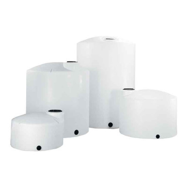
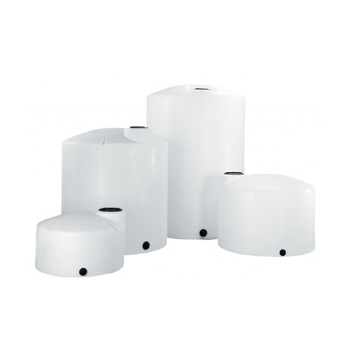
Indoor tank fill operations across the 5-brand catalog typically use moderate-volume vertical tanks where the operator is present during fill and ventilation engineering matters:
- Norwesco vertical chemical storage: the standard indoor chemistry storage. Reference N-40146 1,500 gallon for moderate-volume indoor sodium hypochlorite or aqueous ammonia service; the fill connection is typically a 4-inch top-mounted port with a captor hood positioned over it during fill events.
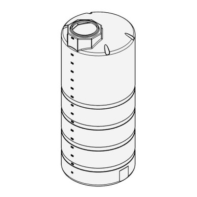
- Snyder Captor double-wall: SPCC-compliant double-wall containment for indoor or partially-enclosed installations. Reference SII-5990102N42 1,000 gallon; the integrated annular containment satisfies indoor secondary-containment requirements and reduces the floor footprint.
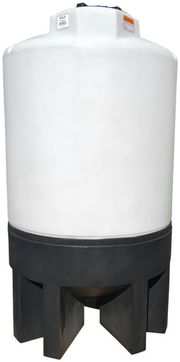
- Norwesco cone-bottom: indoor production-process feed tanks where complete drawdown is part of the operating cycle. Reference N-43852 1,000 gallon 45-degree cone.
The tank itself is identical in indoor versus outdoor service; what changes is the surrounding ventilation engineering. Indoor placement requires the fill-event LEV, the room dilution ventilation per ASHRAE 62.1, and any chemistry-specific or flammability-driven ventilation rate from NFPA 30 or other applicable code. The total room ventilation requirement is the sum of the chemistry-driven and the occupancy-driven minimums.
8. Sensor and Control Architecture for Ventilation Verification
Ventilation systems fail. Fans wear out, dampers stick, ducts plug with deposit, hoods get bumped out of position. The engineering deliverable includes a verification system that detects ventilation failures before they become occupational exposures.
The standard sensor-and-control architecture:
- Air-flow proving switch on each exhaust fan: verifies the fan is actually moving air (not just receiving electrical power). A pressure-differential switch on the fan suction is the typical implementation.
- Air-flow indicator at the captor hood: magnetic gauge or differential pressure indicator visible to the operator. The operator verifies flow is in range before initiating fill.
- Toxic-gas detector at the breathing zone: chlorine, ammonia, hydrogen sulfide, etc., depending on chemistry. Alarm threshold typically at the ACGIH TLV or 50 percent of the OSHA PEL. Multi-point monitor for facilities with multiple chemistries.
- Combustible-gas detector for Class I flammable service: calibrated to the specific chemistry. Alarm at 25 percent of the lower flammable limit (LFL); facility shutdown at 50 percent LFL.
- Interlock with fill-pump control: fill operation cannot start unless ventilation flow proving and gas-detector-clear are both confirmed. Fill operation is automatically stopped if either signal is lost during fill.
The interlock architecture is the difference between a ventilation system that works when it is working and one that works reliably across the operational life. Without the interlock, a clogged duct or a stuck damper allows the fill event to proceed at the same operator-set rate while ventilation has silently failed; with the interlock, the operator gets an immediate fault and the fill cannot begin.
9. Commissioning, Testing, and Annual Verification
The ventilation system requires commissioning and ongoing verification:
- Commissioning: measured airflow at every captor hood, every fan, and every register; comparison to design intent; documentation of any deviation; smoke-test of capture at the fill points to verify the vapor plume is captured.
- Annual airflow verification: repeat measurements with calibrated instrument (hot-wire anemometer or pitot traverse). Trend against commissioning baseline; investigate any drop greater than 10 percent.
- Annual fan inspection: bearings, belts, motor amp draw, fan blade integrity. Replace or rebuild as indicated.
- Quarterly hood inspection: visual inspection for damage, position drift, or accumulated deposit at the hood face; smoke-test recapture verification.
- Quarterly gas-detector calibration: bump-test (verify response to a known gas concentration); full calibration annually using certified gas mixtures.
- Annual interlock test: simulate a ventilation failure and verify the fill-pump interlock prevents fill initiation.
The verification cadence is part of the operational cost of indoor tank fill. The cost is modest — typically $2,000-$8,000 per year for a small to mid-size facility — but skipping it is the mechanism by which a properly-designed ventilation system silently degrades into a non-functional one.
OneSource Plastics ships polyethylene tanks across all 5 brands paired with manufacturer cut sheets, and our engineering team supports indoor-installation ventilation consultation for the room and the LEV at the fill point. List pricing by SKU is published on each product page; LTL freight to your ZIP is quoted separately via the freight estimator or by phone at 866-418-1777. For closely related topics see tank vent selection and vent capacity calculations.
Recommended Tanks for This Guide
Live pricing, updated automatically · estimate freight to your ZIP.