Tank Explosion-Vent and Rupture-Disk Engineering for Pressure Relief: ASME Section VIII UV Stamp Requirements, NFPA 68 Deflagration Vent Sizing, Burst Pressure Selection, and Atmospheric Polyethylene Tank Vent Architecture


The pressure-relief device on an industrial tank is the last-line safety system that protects the tank, the personnel, and the surrounding facility against a pressure-rise event that exceeds the structural design capacity. On pressure-vessel tanks, the relief is typically a code-stamped relief valve or rupture disk under ASME Section VIII Division 1 with the UV stamp. On atmospheric tanks holding flammable or combustible vapors, the relief includes deflagration vents sized per NFPA 68 to release the pressure rise from a confined deflagration before the tank ruptures. On atmospheric polyethylene tanks holding non-combustible chemistry, the architecture is different: standard conservation vents and emergency vents per API 2000 protect against fill-rate and fire-exposure scenarios without the explosion-vent component. This article walks the relief architectures, the selection logic, the burst-pressure mathematics, the disk-replacement cycles, and the procurement implications across the tank-construction landscape.
The framework is grounded in ASME Section VIII Division 1 pressure-vessel code, NFPA 68 standard on explosion protection by deflagration venting, API 2000 venting of atmospheric and low-pressure storage tanks, and the OneSource Plastics 5-brand polyethylene tank catalog (Norwesco, Snyder, Chem-Tainer, Enduraplas, Bushman). List pricing on each polyethylene tank product page; LTL freight quoted to your ZIP via the freight estimator or by phone at 866-418-1777.
1. The Pressure-Relief Architecture by Tank Type
The relief architecture is selected based on the tank construction, the design pressure, the contents flammability, and the regulatory regime. The major architectures:
- The ASME pressure vessel with relief valve. Pressure vessels designed and stamped to ASME Section VIII Division 1 carry a relief device set at or below the maximum allowable working pressure (MAWP). The standard device is a spring-loaded pressure-relief valve that opens at the set pressure and reseats when pressure returns to normal. Capacity is sized to handle the maximum credible pressure-rise event.
- The ASME pressure vessel with rupture disk. Some pressure vessels use a rupture disk in place of, or upstream of, the relief valve. The disk bursts at a set pressure and provides full-bore flow without the valve-seat dynamics. Sites use rupture disks for fast-acting relief, for two-phase service where valve-seat fouling is a concern, or for combination installations where the disk protects the upstream valve seat from the contained chemistry.
- The atmospheric tank with conservation vents and emergency vents per API 2000. Atmospheric tanks (design pressure less than 15 psi, typically less than 2 psi) use conservation vents (pressure-vacuum vents) for normal fill-and-draw breathing and emergency vents for fire-exposure relief. The vents are sized per API 2000 and are not ASME-stamped. The regime is appropriate for atmospheric polyethylene tanks and atmospheric steel tanks.
- The deflagration-vent-equipped tank. Tanks holding combustible dust or flammable vapor mixtures have an additional deflagration vent sized per NFPA 68. The deflagration vent activates if a confined explosion event begins and releases the pressure rise before tank rupture. The vent is sized to limit the peak reduced pressure to a value the tank can withstand.
- The combination architecture. Some installations combine a rupture disk in series with a relief valve. The disk bursts first and the valve handles the relief flow. The combination is used where the contained chemistry would foul the valve seat (corrosive, sticky, or polymerizing materials) so the disk provides the chemistry isolation while the valve provides the reclosable relief.
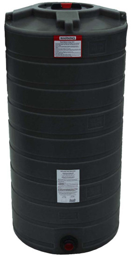
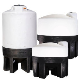
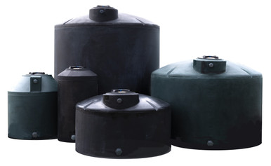
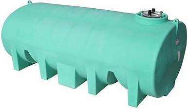
- Reference 5000 gallon polyethylene tank for atmospheric service. Reference N-40164 5000 gallon Norwesco vertical as a typical atmospheric polyethylene tank where the API 2000 vent architecture applies. The polyethylene tank is not a pressure vessel and does not carry an ASME stamp; the vent system is sized per the atmospheric-tank rules.
The architecture choice is consequential. Selecting the wrong architecture for the application produces an installation that does not protect against the credible pressure-rise events.
2. ASME Section VIII Division 1 UV-Stamp Requirements
Pressure-relief devices on ASME pressure vessels carry the UV stamp that certifies compliance with the ASME pressure-relief device code. The UV-stamp requirements:
- The capacity-certification requirement. The relief device must have a capacity (in pounds per hour or standard cubic feet per minute) that is certified by the National Board of Boiler and Pressure Vessel Inspectors. The certification verifies that the actual flow capacity matches the rated capacity used in sizing calculations.
- The set-pressure tolerance specification. The set pressure of the relief device is within a defined tolerance (typically plus-or-minus 3 percent for standard devices, tighter for some applications). The tolerance is verified at manufacture and re-verified at periodic in-service testing.
- The blowdown specification. Spring-loaded relief valves close at a pressure below the set pressure (the blowdown pressure). The blowdown range is specified by code and verified by manufacturer testing. Wide blowdown reduces fluid loss but requires higher pressure rise to open.
- The Code Case-conforming materials. The relief device construction materials are listed in the ASME-approved materials list for the service. Standard valve bodies are carbon steel, stainless steel, or alloy depending on the contained chemistry.
- The marking and traceability. Each UV-stamped device is permanently marked with the manufacturer identifier, the serial number, the set pressure, the rated capacity, and the UV symbol. The marking supports the in-service traceability and the audit trail.
- The Code Case for rupture disk certification. Rupture disks under ASME Section VIII have their own certification path. The disk burst pressure has tolerance bands; the disk capacity has flow coefficients that depend on holder design; the disk material has temperature derating. Each is documented in the disk-manufacturer certification.
- The relief-device sizing under ASME. The relief device size is calculated for the worst-case pressure-rise scenario (heat input from external fire, runaway reaction, blocked discharge with continuing supply, rapid temperature rise of trapped fluid). The largest required capacity governs the device size. The sizing calculation is documented and signed by a qualified engineer.
The UV-stamp regime is the regulatory backbone of pressure-vessel relief. Sites operating ASME pressure vessels maintain the relief-device records as part of the equipment certification and the ongoing inspection program.
3. NFPA 68 Deflagration Vent Sizing
For tanks holding combustible dusts, flammable vapor mixtures, or other deflagration-prone contents, NFPA 68 specifies the deflagration-vent sizing methodology:
- The deflagration phenomenon definition. A deflagration is a subsonic combustion wave that propagates through a fuel-air mixture. In a confined space the deflagration produces a rapid pressure rise that can rupture the containment. The deflagration vent provides a controlled pressure-release path that limits the peak pressure to a value the tank can withstand.
- The Kst characterization for dusts. Combustible dusts are characterized by the deflagration index Kst (in bar-meter-per-second). Higher Kst indicates more energetic dusts (faster pressure rise). The Kst is measured in standardized 20-liter test chambers and tabulated by dust type.
- The Pmax and KG for vapors. Flammable vapor mixtures are characterized by the maximum pressure Pmax and the deflagration index KG. The values are tabulated by gas type and concentration.
- The vent area calculation. NFPA 68 provides equations and worksheet methods to calculate the required vent area as a function of the dust or gas characteristics, the tank volume, the tank pressure-resistance capability (Pred), and the vent panel burst pressure (Pstat). The calculation produces a required vent area in square feet.
- The vent panel construction. Deflagration vents are typically lightweight panels (rupture disks, spring-loaded panels, or hinged-cover constructions) that activate at low pressure (typically 0.5 to 1.5 psig) and provide the calculated vent area. The panels are designed to remain attached or to release safely without becoming projectiles.
- The vent-discharge location and orientation. The vent discharge must be directed to a location where the released material does not endanger personnel or damage adjacent equipment. Discharge to outdoor open area is preferred; indoor venting requires duct extensions to outdoor termination.
- The interaction with structural strength. The deflagration vent sizing depends on the tank's pressure-resistance capability (Pred). Stronger tanks need smaller vents; weaker tanks need larger vents. Atmospheric polyethylene tanks have very low Pred (typically less than 0.5 psig) and would require very large deflagration vents if used for combustible service, which is why polyethylene atmospheric tanks are not used for deflagration-prone contents.
The NFPA 68 framework is the deflagration-protection layer. Its application to a tank is determined by whether the contents pose a deflagration risk; non-deflagration contents do not require the framework.
4. Burst Pressure Selection and Disk Specification
The rupture-disk burst pressure selection is a balance between the protection-pressure requirement and the operational-pressure margin:
- The set-pressure-relative-to-MAWP rule. ASME Section VIII allows the relief-device set pressure at or below the MAWP for single-device installations and at higher percentages for multi-device installations. Standard practice sets the disk burst pressure at the MAWP for primary protection.
- The operational-margin consideration. The disk should burst above the maximum operating pressure with adequate margin. Bursting too close to the operating pressure produces nuisance ruptures from normal pressure fluctuations. Standard practice sets the disk at least 30 to 40 percent above the maximum operating pressure (MOP).
- The disk-burst-tolerance specification. Rupture disks have manufacturer-specified burst tolerances (typically plus-or-minus 5 percent for standard disks, plus-or-minus 2 percent for tight-tolerance disks). The selected nominal burst pressure plus the upper tolerance must remain below the protection threshold.
- The temperature-derating curve. Disk burst pressure varies with temperature. The nominal burst pressure is rated at a reference temperature (typically 72 degrees Fahrenheit). At elevated or reduced temperatures, the actual burst pressure shifts per the manufacturer derating curve. The service temperature is specified to the manufacturer for proper disk selection.
- The cyclic-fatigue consideration. Disks subjected to repeated pressure cycles below the burst pressure can experience fatigue that reduces the eventual burst pressure. Standard disks tolerate operating pressure to about 70 percent of the nominal burst pressure before fatigue concerns. High-cycle service warrants a fatigue-rated disk type.
- The corrosion-and-erosion considerations. The disk material must withstand the contained chemistry without corrosion or erosion that would alter the burst pressure. Standard disk materials (austenitic stainless, nickel alloys, tantalum) are selected based on the chemistry. Disks may include downstream backing or upstream coating for additional chemistry protection.
- The forward-acting versus reverse-acting selection. Forward-acting disks burst from concave-toward-pressure orientation; reverse-acting disks have a domed shape with the pressure on the concave side. Reverse-acting disks have tighter burst tolerance and better fatigue resistance but at higher cost. The selection depends on the operating-pressure-to-burst-pressure ratio and the application criticality.
The disk-specification balance gives an installation with reliable protection performance and minimal nuisance ruptures over the service life.
5. Disk Replacement Cycles and In-Service Inspection
Rupture disks are not lifetime components. The replacement cycles and the in-service inspection determine the disk reliability over time:
- The manufacturer-recommended replacement interval. Most rupture-disk manufacturers recommend periodic replacement (typically 3 to 5 years) regardless of service condition. The replacement is preventive maintenance against age-related degradation.
- The operating-conditions-based replacement. Severe service (high temperature, aggressive chemistry, high pressure-cycle count) shortens the replacement interval. Site procedures may specify replacement intervals as short as 1 year for severe service.
- The post-burst inspection of associated equipment. When a disk bursts, the relief event is investigated to identify the root cause. The downstream piping, the relief header (if any), and the receiving vessel are all inspected for damage. The disk is replaced and the protection is verified before return to service.
- The visual-inspection observation pattern. Disks are inspected visually for visible damage (deformation, corrosion, holder seal degradation) at the same cadence as other relief-device inspections. Visual abnormalities trigger early replacement or further investigation.
- The pre-bulge measurement on reverse-acting disks. Some advanced inspections measure the pre-bulge dimension of reverse-acting disks against the manufacturer original specification. Out-of-specification measurements indicate fatigue progression and warrant replacement.
- The downstream sensor for burst detection. Modern installations include a downstream pressure switch or membrane-rupture sensor that signals a disk burst to the control system. The signal supports immediate operator response and avoids continued operation with a ruptured protection device.
- The replacement-installation discipline. The disk replacement is performed per a written procedure with the disk-manufacturer instructions. Improperly installed disks (incorrect orientation, improper bolt torque, damaged sealing surface) burst at incorrect pressures and compromise the protection. Installation training and procedure adherence are critical.
The disk-replacement program is the long-term-reliability layer of the relief installation. Sites that maintain rigorous replacement schedules produce installations that protect over decades; sites that defer replacement accept progressively higher risk of protection failure.
6. Why Atmospheric Polyethylene Tanks Use a Different Architecture
Atmospheric polyethylene tanks operate in a different relief regime than ASME pressure vessels. The reasons and the architectural differences:
- The atmospheric-design-pressure foundation. Polyethylene tanks are designed for atmospheric pressure (typically less than 1 psig design). The structural design does not contemplate the pressure-rise events that ASME pressure vessels handle. The relief must therefore prevent any significant pressure rise rather than handle it.
- The conservation-vent function. Conservation vents (pressure-vacuum vents) protect against the low-pressure events of normal operation: pressure rise from fill-rate displacement of vapor and vacuum from draw-rate suction. The vents open at very low set pressures (0.5 to 2.0 ounces per square inch) and provide adequate flow for the maximum fill and draw rates.
- The emergency-vent function for fire exposure. Emergency vents are sized larger than conservation vents to handle the pressure rise from external-fire heat input. API 2000 specifies the emergency-vent capacity calculation based on the tank wetted-area heat-input. The emergency vents are typically weighted manhole covers or large hinged covers that lift on small pressure rise.
- The non-applicability to combustible contents. Polyethylene tanks are not used for combustible-dust storage and are not preferred for flammable-vapor storage. The combustible-vapor tank, if polyethylene, would require deflagration venting that the polyethylene cannot effectively provide due to the low Pred. The chemistry-mismatch is the practical reason flammable-vapor tanks are typically steel or fiberglass with appropriate relief.
- The tank-shell as relief path. Some polyethylene-tank failure modes involve the tank shell itself acting as the pressure-relief path: a localized weak point ruptures before the bulk shell loses containment. This is a failure mode rather than a designed relief but it informs the operational margin maintained on polyethylene tanks.
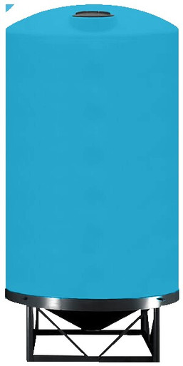
- Reference 1500 gallon polyethylene tank with vent architecture. Reference N-40154 1500 gallon Norwesco vertical as a typical mid-volume polyethylene tank where the conservation-and-emergency-vent architecture applies. The vents are specified at procurement based on the planned fill and draw rates and the worst-case fire-exposure scenario.
- The polyethylene-tank chemistry exclusions. Polyethylene tanks are not used for chemistry that would generate the deflagration or the rapid-pressure-rise scenarios that ASME relief addresses. The chemistry compatibility framework that drives polyethylene tank selection inherently excludes the chemistries that would push the relief beyond conservation-and-emergency vents.
The polyethylene-tank vent architecture matches the polyethylene-tank service envelope. Sites that operate polyethylene tanks for compatible chemistry build the vent system per API 2000 and do not need the ASME relief-device infrastructure.
7. Procurement Implications and Tank-Construction Selection
The relief architecture has implications for tank construction selection at procurement:
- The chemistry-and-pressure decision tree. The first procurement question is the operating pressure. Atmospheric chemistry favors polyethylene or atmospheric steel. Pressure chemistry above 15 psig requires ASME pressure-vessel construction (steel, alloy, or specialty plastics with appropriate code stamping).
- The combustibility-and-flammability decision tree. The second procurement question is the chemistry combustibility. Combustible dusts and flammable vapors warrant deflagration-vent-capable construction. Non-combustible chemistry uses standard vent architecture.
- The temperature-and-thermal-cycle decision tree. The third procurement question is the temperature regime. Hot-service chemistry (above 140 degrees Fahrenheit continuous) typically requires steel construction. Moderate-temperature chemistry suits polyethylene with attention to the upper temperature limit.
- The size-and-economic-decision tree. The fourth procurement question is the size and the economic case. Polyethylene is typically lower capital cost than steel for moderate-size atmospheric tanks. ASME pressure vessels are higher capital cost regardless of size due to the code-stamp requirements.
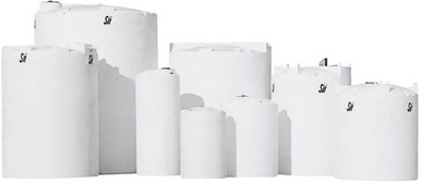
- The OEM-and-supplier-decision. Once the construction type is chosen, the brand and supplier selection follows. For polyethylene atmospheric tanks, the OneSource Plastics 5-brand catalog (Norwesco, Snyder, Chem-Tainer, Enduraplas, Bushman) provides procurement options across sizes and configurations. For ASME pressure vessels, specialty fabricators with ASME shop certificates provide the construction.
- The relief-device specification at procurement. The relief devices (conservation vents and emergency vents for polyethylene tanks; relief valves and rupture disks for ASME pressure vessels) are specified at the same time as the tank. The relief-device specification ensures the protection is sized to the operating conditions and is procured as part of the integrated installation.
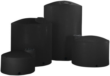
- Reference 1000 gallon polyethylene tank for general atmospheric service. Reference N-40152 1000 gallon Norwesco vertical as a typical atmospheric tank where the conservation-and-emergency-vent specification follows from the chemistry and the operating profile.
The procurement decisions are integrated across tank construction, relief architecture, and chemistry. Sites that engage all three at procurement produce installations matched to the service requirements; sites that procure incrementally produce installations with potential mismatches between construction, relief, and operation.
8. Operational Discipline and Inspection Program
The relief installation is verified by ongoing inspection and testing. The discipline:
- The annual relief-valve testing. ASME-stamped relief valves are typically tested annually. The test verifies the set pressure, the seat tightness, and the blowdown. Out-of-specification valves are repaired or replaced. The test is documented and the valve tag is updated.
- The conservation-vent inspection cadence. Conservation vents on atmospheric tanks are inspected semi-annually to annually for proper operation. The inspection verifies the pallet movement, the seal integrity, and the flame-arrestor cleanliness (if applicable). Inspections are documented with photographs and observations.
- The emergency-vent inspection. Emergency vents are inspected at the same cadence as the tank shell inspection (typically every 5 to 10 years for atmospheric tanks). The inspection verifies the cover hinge function and the seal integrity.
- The deflagration-vent inspection. Deflagration vents on combustible-service tanks are inspected per the manufacturer recommendation and per any applicable site procedure. The inspection verifies that the vent panel has not been altered, painted over, or otherwise compromised.
- The post-event investigation discipline. Any relief event (relief valve lift, disk burst, emergency vent activation) triggers an investigation to identify the cause and prevent recurrence. The investigation findings drive operational changes, equipment changes, or procedural changes.
- The documentation retention. The relief-system records (specifications, inspections, tests, replacements, events) are retained for the equipment service life. Regulatory inspections and audit reviews access the records to verify the protection program.
- The training program for operators. Operators who interact with the relief system (maintenance, inspection, post-event response) are trained on the equipment and the procedures. The training is documented and refreshed periodically.
The operational discipline transforms the procurement-stage relief installation into the multi-decade protection that the original engineering envisioned.
9. The Pressure-Relief Engineering Conclusion
The pressure-relief architecture matches the tank construction, the chemistry, the operating pressure, and the regulatory regime. ASME pressure vessels use UV-stamped relief valves and rupture disks per Section VIII Division 1. Combustible-content tanks add deflagration vents per NFPA 68. Atmospheric polyethylene tanks use conservation vents and emergency vents per API 2000. Each architecture serves the service envelope of the corresponding tank construction; mismatches between architecture and tank construction produce installations that do not protect against the credible pressure-rise events. Sites that select the right architecture at procurement and maintain the inspection-and-replacement discipline produce installations that operate safely over decades; sites that shortcut the framework accept the operational risk that the protection may fail when needed.
OneSource Plastics ships polyethylene tanks across the 5-brand catalog (Norwesco, Snyder, Chem-Tainer, Enduraplas, Bushman) for atmospheric chemistry-storage applications with conservation-vent and emergency-vent architectures sized to the service. Pressure-vessel applications and combustible-content applications are referred to specialty fabricators with the appropriate code-stamp infrastructure. List pricing on each polyethylene tank product page; LTL freight to your ZIP via the freight estimator or by phone at 866-418-1777.
Recommended Tanks for This Guide
Live pricing, updated automatically · estimate freight to your ZIP.