Tank Vent Line Drainage Engineering: Low-Point Pocketing Prevention, Continuous Slope Specification, Trap Removal, and Drip-Leg Sumps for Condensate Capture on Atmospheric and Conservation-Vented Storage Tanks


The tank vent line is the small-diameter steel or thermoplastic pipe that runs from the tank-top vent fitting to the discharge point, typically the eave of a building or an outdoor location safe for vapor release. The vent line carries vapor in two directions during normal tank operation: outbound when the tank is filled and inbound when the tank is drawn down, and continuously inbound or outbound when chemistry vapor pressure changes drive breathing. The vent line is small in diameter and modest in cost relative to the tank itself, but a vent line plumbed without attention to drainage develops liquid pockets, ice plugs in cold climates, and chemistry condensate accumulation that ultimately blocks the vent and triggers tank pressure or vacuum failure.
This article walks the engineering of vent line drainage, the continuous-slope specification that prevents pocketing, the trap removal discipline that eliminates accidental low points, and the drip-leg sump design that captures condensate without obstructing the vent flow path. The discussion is grounded in vent system fundamentals, manufacturer technical specifications across the 5-brand catalog of Norwesco, Snyder, Chem-Tainer, Enduraplas, and Bushman, and field practice for chemistry-service tank installations. List pricing on each tank product page; LTL freight quoted to your ZIP via the freight estimator or by phone at 866-418-1777.
1. The Vent Line Drainage Problem
The vent line drainage problem arises from condensation, infiltration, and chemistry vapor characteristics:
- Water vapor condensation in the vent line. Tank breathing pulls humid ambient air into the headspace during draw-down. The humid air contacts the cooler vent line walls (especially in early morning when ambient cools faster than tank chemistry) and water vapor condenses on the inner pipe wall. The condensate runs down by gravity to the lowest point in the vent line. If the vent line slopes back toward the tank or has level segments, the condensate accumulates in the line.
- Chemistry vapor condensation in the vent line. Volatile chemistry vapor (hypochlorite, ammonia, dilute acid, hydrogen peroxide) carries water and reactive constituents that condense in the vent line on the cooler discharge side. The chemistry condensate is corrosive to most vent line materials and is hazardous to handle.
- Wind-driven rain entry at the discharge end. Wind-driven rain at the vent discharge can enter the vent line directly. Without a discharge geometry that excludes water (gooseneck, screen with hood, side-discharge cap), the rain runs down the inside of the vent line and accumulates at any low point.
- The pocketed vent line failure cascade. Once a low-point pocket forms and accumulates liquid, the vent flow path through that section is partially or fully obstructed. The tank breathing pressure or vacuum builds against the partial obstruction. In severe cases the tank reaches the upper or lower pressure limit and the tank wall flexes (vacuum-induced collapse) or the manway gasket lifts (pressure-induced lift). Tank failures attributed to "vent failure" are typically pocketed vent line failures.
- The cold-climate ice-plug variant. In freezing climates the condensate freezes in any low-point pocket, producing a hard ice plug that fully blocks vent flow. The plug typically forms at the first overnight freeze after a humid day. Vent failures spike in early winter as accumulated condensate from the autumn freezes hard.
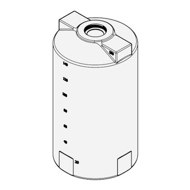
- Reference tank for vent line geometry. Reference N-40164 5000 gallon Norwesco vertical as the typical mid-volume tank where vent line drainage planning matters operationally. The vent fitting at the tank top and the discharge at the building eave or outdoor stand-off establishes the vent line route that the drainage discipline must accommodate.
The vent line drainage problem is addressed through routing geometry, slope specification, and condensate capture design. The principles are simple but they require attention at the time of vent line installation; retrofit corrections to a poorly routed vent line are disruptive.
2. The Continuous Slope Specification
The continuous slope specification is the primary defense against vent line pocketing:
- The minimum slope angle. The vent line must slope continuously at minimum 1/4 inch per foot (approximately 1.25 percent grade) along its full length. The slope can run toward the tank (so condensate drains back into the chemistry through the vent fitting) or toward the discharge (so condensate exits the vent line at the discharge end with proper drip-leg capture). The specification is one direction or the other but never level and never reverse.
- The slope toward the tank approach. When the vent slope runs toward the tank, condensate drains directly into the chemistry. This works for chemistry where small volumes of water dilution are acceptable (potable water tanks, brine tanks, fertilizer solution tanks). It does not work for chemistry where water entry causes problems (concentrated acids that exotherm with water, chemistry that hydrolyzes, or chemistry that stratifies).
- The slope away from the tank approach. When the vent slope runs away from the tank toward the discharge end, condensate exits the vent at the discharge or is captured in a drip-leg sump near the discharge. This approach is required for chemistries where water entry into the chemistry is unacceptable. The drip-leg sump captures the condensate for periodic disposal.
- The route planning discipline. The vent line route is planned at design time with the slope specification in mind. The route runs in straight slopes from one elevation transition to another with no unintended low points between. Each straight run has a defined slope direction; transitions occur only at planned high points or low points where elevation changes are unavoidable.
- The pipe support discipline for sustained slope. The vent line pipe sags between supports under its own weight, the weight of any condensate, and the weight of any external loads (snow accumulation, ice loading, accidental contact). The pipe support spacing must be tight enough that sag does not create local low points. For 1.5-inch and 2-inch vent line pipe in steel, supports at 8-foot maximum spacing typically prevent significant sag.
- The thermal expansion and contraction allowance. Vent line pipe expands and contracts with ambient temperature swings. A 100-foot run of steel pipe sees approximately 1 inch of length change between summer and winter. The route includes an expansion loop, an offset, or an expansion fitting that accommodates the length change without distorting the slope or creating new low points.
The continuous slope specification establishes the vent line as a self-draining flow path. Properly routed vent lines maintain their drainage function across decades of service without operator intervention.
3. Trap Removal and Anti-Pocketing Discipline
The vent line route must avoid the typical traps that produce accidental low points:
- The U-bend trap that contractors often install. Vent line installation contractors familiar with plumbing drainage habits sometimes install a U-bend or a P-trap on the vent line as a "vapor barrier" or "rodent barrier." The trap holds liquid in its lowest section by design and that liquid blocks vent flow. The U-bend is incorrect on a tank vent line and must be removed if found. Vapor barrier and rodent exclusion are achieved through the discharge geometry, not through traps.
- The unintended sag at long pipe runs. A long horizontal pipe run between two supports sags in the middle. The sag low point can hold liquid even when the support elevations are correctly aligned. The fix is intermediate supports or pipe stiffening. A properly sloped pipe still benefits from intermediate supports to maintain the slope geometry under load.
- The wrong-direction slope at a fitting transition. Vent line fittings (elbows, tees, reducers, couplings) sometimes shift the pipe slope at the fitting if the fitting is not aligned with the design slope. The discipline is that every fitting installation includes a level check or slope check after installation; misaligned fittings are corrected before the system is buried, insulated, or trim-finished.
- The accidental low-point at a building penetration. Where the vent line passes through a wall or roof penetration, the penetration must allow the pipe to maintain its slope. A penetration that pinches the pipe horizontal or that constrains the pipe to a fixed geometry can introduce a low point. Penetrations include sleeves with adequate clearance for the pipe slope.
- The dead-end branch trap. A vent line branching off the main run to serve a secondary instrument or fitting can create a dead-end low point if the branch slopes toward a closed end. The discipline is that branches either slope back into the main run with a continuous slope or include a drip-leg sump at the branch low point.
- The retrofit trap from added equipment. Equipment added to a vent line after original installation (a flame arrester, a vent valve, a level instrument) can introduce new low points at the equipment installation. The discipline is that equipment additions are designed with the same continuous slope specification as the original vent line, and the slope is verified after installation.
The trap removal and anti-pocketing discipline is mostly about avoiding the typical errors. Once a vent line is correctly installed without traps and with continuous slope, the discipline shifts to verification at retrofit events and during periodic inspection.
4. Drip-Leg Sump Design for Condensate Capture
The drip-leg sump captures condensate at the vent line low point in the away-from-tank slope configuration:
- The sump location at the discharge-side low point. The drip-leg sump is installed at the lowest point of the vent line on the discharge side of the slope, typically near but not at the discharge end. The sump is a vertical pipe section with a closed bottom and a drain valve.
- The sump sizing for accumulated condensate volume. The sump volume is sized for the expected condensate accumulation between drain intervals. For a typical 5000 gallon chemistry tank with 100 feet of vent line in a humid climate, condensate accumulation is roughly 0.5-2 gallons per month. A sump volume of 2-5 gallons accommodates a quarterly or semi-annual drain cadence.
- The sump drain valve specification. The drain valve is a chemistry-compatible ball valve with appropriate elastomer seals. The valve closure must be positive (no slow leak that would dribble condensate continuously). The valve handle is accessible from grade level for periodic drain operation.
- The sump material compatibility. The sump material matches the vent line material and the chemistry condensate composition. For hypochlorite vapor service the sump is typically PVC, CPVC, or 316L stainless. For ammonia vapor service the sump is 304 or 316 stainless. For hydrocarbon vapor service the sump is steel with appropriate coating.
- The sump drainage discipline. The sump drain valve is opened at scheduled intervals and the condensate is captured into a chemistry-compatible drum or drain. The drain is logged with date, volume, and visual condition of the condensate. Unusual volume or appearance triggers investigation of vent line condition.
- The sump as inspection point. The sump location also serves as the inspection access point for vent line condition. Camera or borescope inspection through the sump assesses the upstream and downstream pipe condition. The combined drain and inspection function justifies the sump installation cost.
The drip-leg sump converts vent line condensate from a hidden accumulation into a managed waste stream. The capital cost is modest; the operational benefit is substantial.
5. Cold-Climate Vent Line Special Provisions
Cold-climate operation introduces additional vent line considerations:
- The freezing-point analysis on accumulated condensate. Pure water condensate freezes at 32 F. Chemistry condensate (hypochlorite, ammonia, dilute acid) has a depressed freezing point that varies by chemistry concentration. The freezing point analysis establishes the lowest expected ambient temperature where condensate will be liquid versus solid.
- The heat trace cable on freeze-prone segments. Vent line segments where condensate is expected to freeze in winter are heat-traced with self-regulating heat tape rated for the climate temperature range. The heat trace power is typically 5-10 W per linear foot, controlled by ambient or pipe-temperature sensor.
- The insulated jacket over heat-traced segments. The heat-trace cable is jacketed with closed-cell foam insulation rated for the climate temperature range, with a weatherproof outer jacket. The insulation reduces heat trace power consumption and extends the protected temperature range.
- The increased slope for faster drainage. Cold-climate vent lines benefit from slope above the 1/4 inch per foot minimum, sometimes 1/2 inch per foot, which moves condensate to the drainage point faster before freezing has time to occur. The increased slope is achieved through routing planning at design time.
- The discharge end snow and ice protection. The vent discharge in cold climates must exclude snow accumulation and ice formation. A side-discharge cap with screen and hood, mounted with the discharge facing prevailing wind direction, prevents snow ingress. Periodic winter inspection verifies the discharge is clear.
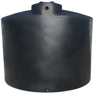
- Reference tank for cold-climate operation. Reference N-41524 2500 gallon Norwesco with the standard tank-top vent fitting in a cold-climate installation as the case where vent line freeze prevention applies. The vent line provisions are independent of tank model and apply across the catalog.
The cold-climate provisions add capital cost (heat trace, insulation, increased slope routing) but eliminate the winter ice-plug failure mode that otherwise dominates cold-climate vent line operations.
6. Material Selection for Vent Line Pipe
The vent line pipe material is selected to match the chemistry vapor exposure and the climate conditions:
- Galvanized steel pipe. Galvanized steel is the lowest-cost vent line material for water-service tanks and tanks with low-aggression chemistry vapor. The galvanized coating extends service life relative to plain steel by 10-20 years in typical outdoor exposure. The material is widely available and easily field-fabricated.
- Schedule 40 PVC pipe. PVC handles hypochlorite, dilute acids, and many oxidizer vapors at ambient temperature. PVC is the standard for chemistry-service vent lines where steel is incompatible. PVC requires UV protection in outdoor exposure (paint or jacketing) and has temperature limits below 140 F for sustained service.
- Schedule 80 CPVC pipe. CPVC handles higher temperatures than PVC (up to 200 F sustained) and equivalent or better chemistry compatibility. CPVC is the standard for warm-service vent lines and for certain aggressive chemistries where PVC service life is marginal.
- Stainless steel pipe. 304 and 316L stainless steel handle ammonia vapor, chlorine vapor, peroxide vapor, and most oxidizer vapor service. Stainless is the premium option where chemistry compatibility eliminates other choices. The cost is 5-10x carbon steel or PVC.
- HDPE pipe. HDPE handles a wide chemistry range and is suitable for buried vent runs and underground geometry. HDPE is less common for above-grade vent lines but appropriate where the chemistry compatibility chart selects it.
- The pipe compatibility cross-check against chemistry vapor. The vent line material is selected against the chemistry vapor composition using the manufacturer chemistry compatibility chart. The vapor compatibility differs from liquid compatibility because the vapor is typically more dilute and at different temperature than the liquid; the manufacturer chart specifies vapor service if relevant.
The material selection drives the vent line capital cost and the long-term reliability. Premium materials cost more upfront but produce vent lines that hold integrity across the chemistry-service tank life.
7. Inspection and Maintenance Cadence
The vent line inspection and maintenance cadence supports long-term reliable operation:
- Monthly visual inspection. Walk the vent line route monthly. Look for visible damage, accumulated water at any low point, dripping at fittings, ice formation in cold weather, and condition of supports and insulation. Log findings.
- Quarterly drip-leg sump drain. Drain the sump quarterly (or more frequently in humid or high-vapor-pressure chemistry service). Log volume, appearance, and any chemistry indicator. Disposal per chemistry waste protocol.
- Semi-annual flow test. Verify vent flow at semi-annual intervals by adding small water charge to the tank and observing pressure stabilization timing, or by direct flow measurement at the vent discharge with calibrated probe. Slow stabilization indicates partial obstruction; immediate investigation is warranted.
- Annual inspection of pipe and supports. At annual inspection examine all pipe sections for corrosion, UV degradation, mechanical damage, and support integrity. Replace damaged segments. Re-paint or re-jacket as needed for UV-exposed segments.
- 5-year deep inspection with bore camera. Every 5 years run a bore camera through the vent line from the discharge or sump. Examine for accumulated deposits, scale, corrosion product buildup, or unexpected obstructions. The 5-year interval is the typical interval before chemistry-service vent lines develop noticeable internal degradation.
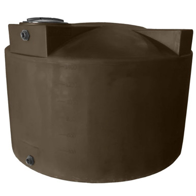
- Reference 1500 gallon vertical tank for annual cadence. Reference N-40144 1500 gallon Norwesco vertical as the smaller chemistry-service tank where the same vent line cadence applies. The vent line installation and maintenance discipline scales directly across tank sizes.
The inspection and maintenance cadence is the operational discipline that holds vent line integrity across the multi-decade tank service life. The cadence is modest in time and labor but substantial in failure-mode avoidance.
8. The Vent Line Drainage Engineering Conclusion
Vent line drainage engineering is the small-pipe discipline that prevents the large-tank failure mode. The continuous slope specification, the trap removal discipline, the drip-leg sump for condensate capture, the cold-climate freeze provisions, the material selection for chemistry compatibility, and the inspection and maintenance cadence are the elements that produce vent lines that hold their function for decades. The capital and operational cost of the vent line discipline is small relative to the tank cost; the consequence of failure is large because tank breathing failures escalate quickly to tank wall or manway damage.
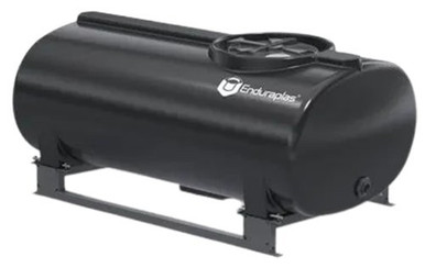
OneSource Plastics ships polyethylene tanks across the 5-brand catalog (Norwesco, Snyder, Chem-Tainer, Enduraplas, Bushman) with manufacturer-published vent fitting specifications. The vent line plumbing downstream of the tank fitting is the customer site responsibility, and is engineered to the principles outlined here. List pricing on each product page; LTL freight to your ZIP via the freight estimator or by phone at 866-418-1777. For related vent engineering see vent type and sizing math and tank plumbing system design.
Recommended Tanks for This Guide
Live pricing, updated automatically · estimate freight to your ZIP.