Calibrated Batch Dosing Pump Integration With Polyethylene Storage Tanks: Drawdown Calibration Methodology, Stroke-Length Verification, Slip Curves, and the Annual Verification Cadence That Holds a Pump to Its Nameplate Across the Service Life

The chemical metering pump on a polyethylene tank installation is the device that translates the operator's setpoint — say, 12 ounces per minute of 12.5 percent sodium hypochlorite — into actual delivered volume. The pump's nameplate accuracy is typically claimed at plus or minus 1 percent at the rated condition. The field-installed pump rarely runs at nameplate accuracy. Suction-line air, valve fouling, diaphragm wear, stroke-length drift, and changes in fluid viscosity or specific gravity all push the pump's actual output away from its setpoint. The standard field problem on a tank installation is not pump selection (which is widely documented); it is pump calibration and verification — establishing what the pump actually delivers, against the chemistry it is delivering, on the day it is being used.
This article walks the engineering protocol for calibrating and periodically verifying a chemical dosing pump on a polyethylene-tank installation. The disciplines covered: drawdown calibration methodology and the calibration column, stroke-length verification and the linear-output assumption, slip curves on diaphragm pumps versus peristaltic pumps, viscosity and specific-gravity correction, the calibration log and trending discipline, and the annual verification cadence that holds a pump to its nameplate across the service life. References cited include AWWA M20 (water chlorination), AWWA C512 (air-and-vacuum valves; relevant to pump suction), HI 7.1-7.5 (Hydraulic Institute pump standards), and ANSI/AWWA G300 (water-treatment plant operation guidelines).
1. The Drawdown Calibration Method: The Field Standard
Drawdown calibration is the standard method for verifying actual pump output. The procedure: a calibration column (a graduated transparent vessel of known volume per inch) is installed on the pump suction line in place of the normal suction connection to the tank. The pump runs at the setpoint condition, and the operator measures the time required to draw a specified volume from the column. Output is computed as volume divided by time.
The calibration column is sized to the pump's expected output. For a pump rated 0.5 gallons per hour, a 250 mL column with 1 mL graduations gives a 30-second draw at 30 mL/30s = 0.5 GPH. For a pump rated 5 GPH, a 1,000 mL column with 10 mL graduations gives a similar resolution. Common column sizes are 100, 250, 500, and 1,000 mL.
The procedure step-by-step:
- Close the suction-side isolation valve to the tank.
- Open the calibration column inlet valve and fill the column from the tank to the upper graduation.
- Close the column-fill valve and open the column-to-pump valve.
- Start the pump at the setpoint and start a stopwatch.
- Stop the stopwatch when the column drains to a known lower graduation. Record time and volume.
- Compute output: volume per unit time, converted to operator units (GPH, mL/min, ounces per minute).
- Repeat 3 times and take the median.
- Restore the suction line to tank-feed configuration. Verify column-fill valve is closed.
The drawdown method has two failure modes that must be controlled. First, suction-side air entrainment from leaky fittings or an under-flooded suction inflates apparent output (the pump appears to deliver more because air takes up volume in the column drawdown but does not get pumped). Second, fluid temperature or viscosity changes between the column and the tank suction can introduce a small error. Both failures are eliminated by verifying the suction line is air-free before starting the column draw and by performing the calibration at the operating fluid temperature.
2. Stroke-Length Verification and the Linear-Output Assumption
Diaphragm metering pumps deliver output proportional to stroke length and stroke frequency. The relationship is approximately linear: 50 percent stroke length and 100 percent frequency delivers roughly the same output as 100 percent stroke and 50 percent frequency. The linearity assumption is the basis for tuning a pump to a target output via the stroke-length and frequency knobs.
The linearity assumption breaks down at the extremes. Below roughly 10-20 percent stroke length, the diaphragm displacement is too small to fully open the suction and discharge check valves on every stroke; output drops below the linear prediction. Above roughly 90 percent stroke, the diaphragm motion approaches its mechanical limit and the over-extension causes accelerated wear. Operating practice is to keep stroke length in the 30-90 percent range and adjust frequency for fine output control.
The stroke-length verification protocol: at install and then quarterly, run the drawdown calibration at three stroke lengths (30, 60, 90 percent) at fixed frequency. The three drawdown results should fall on a near-linear line. A non-linear pattern indicates check-valve fouling, diaphragm wear, or a leaking suction connection. The trended slope of the linear fit is the pump's actual stroke-length-to-output gain; this gain drifts as the pump ages and is the leading indicator of impending pump-rebuild requirements.
3. Slip Curves: Diaphragm vs Peristaltic vs Gear
Pump slip is the difference between theoretical output (geometric displacement times stroke or revolution count) and actual output. Slip varies by pump architecture and by operating conditions.
Diaphragm pump slip. The check valves on the suction and discharge sides do not seal instantaneously. A small amount of fluid back-flows through the partially-open valve on each stroke reversal. Slip is typically 1-3 percent at normal discharge pressures and rises with discharge pressure (higher pressure forces more back-flow during the brief valve transition). Slip versus discharge pressure is a near-linear curve; the manufacturer's data sheet provides the curve for the rated condition. Field calibration should be performed at the actual operating discharge pressure, not at zero pressure.
Peristaltic pump slip. The flexible tube is occluded by the rollers; theoretically there is no slip because the rollers physically squeeze the tube closed. Practical slip is 0.5-1 percent at moderate pressure and rises if the tube is worn (incomplete closure) or if the pump is operated above the tube's pressure rating (the tube re-opens between rollers). Slip in peristaltic pumps is more a tube-condition diagnostic than a steady-state operational characteristic; trended slip rising over time signals tube replacement is approaching.
Gear pump slip. Internal leakage through the gear-to-housing clearance is the slip mechanism. Slip rises with discharge pressure and with fluid temperature (lower viscosity at higher temperature increases leakage). Slip is also chemistry-dependent because the gear-to-housing clearance can grow as the gear or housing chemically wears. Gear pumps require more discipline in slip-tracking than diaphragm or peristaltic.
The slip curve is the practical reason calibration cannot be done once and forgotten. Slip varies with discharge pressure, with fluid temperature, and with pump-component wear. The drawdown calibration measures actual output under actual conditions; the linearity-and-frequency tuning uses the calibrated output as the reference.
4. Specific-Gravity and Viscosity Correction
Pump output in volumetric units (GPH, mL/min) is independent of fluid density to first order. Pump output in mass units (pounds per hour, kg/hour) is volumetric output times specific gravity. The chemistry-feed application is normally specified in mass-per-time terms (pounds of free chlorine per day, mg of antifoam per liter of process), so the conversion from volumetric pump output to mass dosing requires a current value of the chemistry's specific gravity.
The standard chemistries on tank installations and their specific-gravity ranges:
- Sodium hypochlorite 12.5 percent: SG approximately 1.20 fresh, drifting toward 1.16 as the bleach degrades. Mass-dose calculations using fresh-bleach SG against degraded inventory under-deliver chlorine by 3-4 percent.
- Sulfuric acid 93-98 percent: SG 1.84 (98 percent), 1.83 (96 percent), 1.81 (93 percent). The narrow concentration range produces a meaningful SG variation.
- UAN-32 (urea-ammonium nitrate fertilizer): SG approximately 1.32 at 60 F. Temperature variation matters; SG drops about 0.005 per degree F rise.
- Sodium hydroxide 50 percent: SG approximately 1.53 at 60 F. Temperature sensitivity is moderate.
- Polymer flocculants: SG typically 1.0-1.05; viscosity often 100-1000 centipoise, which changes pump output via the viscosity-pressure relationship rather than via SG.
Viscosity affects pump output more for diaphragm and gear pumps than for peristaltic. High-viscosity fluid (over 100 cP) flows more slowly through the suction line and check valves; the pump may not fully fill its diaphragm chamber on each stroke at high frequency, reducing volumetric output. The correction is to slow the pump frequency until the fluid has time to fill the chamber. Manufacturer data sheets provide viscosity-correction curves; field calibration captures the actual viscosity-corrected output.
5. The Calibration Log and Trending Discipline
A single calibration measurement is a snapshot. A trended calibration history is a maintenance leading-indicator and a regulatory-defense document. The calibration log captures, for each calibration event:
- Date and operator.
- Pump tag number and model.
- Tank identification and chemistry.
- Chemistry concentration and current SG (verified hydrometer reading or from delivery certificate).
- Fluid temperature at calibration.
- Setpoint stroke length and frequency.
- Discharge pressure at calibration.
- Calibration column volume drawn and time elapsed (3 measurements; report median).
- Computed actual output.
- Setpoint output (target).
- Deviation (actual minus setpoint, percent).
- Action taken if deviation exceeds tolerance (rebuild, re-tune, replace tubing, etc.).
The trending discipline plots deviation over time. A drift trend (deviation gradually growing in one direction) indicates ongoing component wear and predicts the rebuild horizon. A noisy non-trending pattern indicates measurement variability or chemistry variation rather than pump degradation. A step-change indicates a discrete failure (check-valve fouling, suction air leak) that needs immediate investigation.
Regulatory inspections (NSF, state drinking water primacy agency, USDA process-water audit) routinely review the calibration log as evidence of operational control. A 12-month log with consistent monthly calibration entries and clear corrective-action notes for any out-of-tolerance event is the standard documentation a regulator looks for. A blank or sparse log is a finding regardless of whether the actual operation is sound.
6. Tank Selection for Dosing-Pump-Integrated Service
The 5-brand polyethylene catalog includes products commonly paired with chemical metering pumps for water treatment, agricultural fertigation, and industrial process dosing:
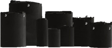
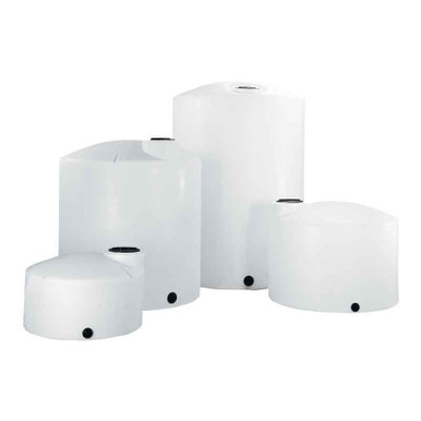
- Norwesco vertical chemical storage: the standard chemical day-tank for dosing-pump suction. Reference N-40146 1,500 gallon for moderate-volume bulk and N-40164 5,000 gallon for larger-volume bulk where the dosing pump runs from a downstream day-tank.
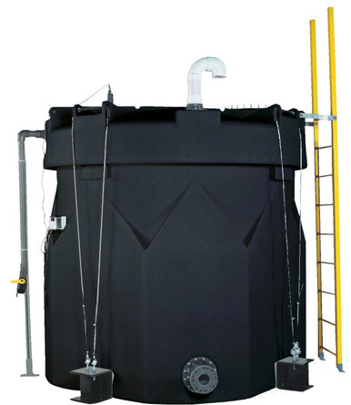
- Snyder Captor double-wall: SPCC-compliant containment for hazardous chemistry feed. Reference SII-5990102N42 1,000 gallon; the dosing-pump suction connects to the inner shell with appropriate bulkhead-fitting routing through the annular space.
- Norwesco cone-bottom: the cone geometry pairs well with low-flow dosing pumps because the suction line draws from the lowest tank point and reduces sediment uptake. Reference N-43852 1,000 gallon 45-degree cone; sediment collection at the cone tip should be drained periodically rather than allowed to enter the dosing-pump suction.
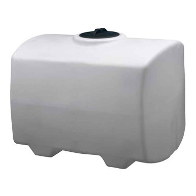
- Bushman water: agricultural-fertigation feed for foliar spray or drip-line injection systems. Reference BM-WW-1500-GL-NAT 1,500 gallon; the dosing pump injects nutrient stock into the irrigation main line and the calibration discipline is the same as in chemical-feed service.
The dosing pump selection itself (peristaltic vs diaphragm vs progressive cavity vs gear) is covered in our metering-pump-selection article; this article focuses on the calibration-and-verification discipline that operates on top of whatever pump architecture is selected.
7. The Annual Verification Cadence
The recommended verification cadence for a metering pump on chemical-tank service:
At install (commissioning): Full drawdown calibration at 3 stroke lengths and 3 frequencies (9 data points). Establish the linearity of stroke-length-to-output. Verify discharge pressure matches the design condition. Document the baseline calibration curve. Sign-off by the install contractor and the receiving operator.
Monthly (in-service): Single-point drawdown calibration at the operating setpoint. Compare to the most recent prior measurement and to the baseline. Trend the deviation. Adjust setpoint to compensate for slip drift if within acceptable range; trigger maintenance if outside acceptable range.
Quarterly: Three-point drawdown at the three baseline stroke lengths to re-validate linearity. Inspect suction-line check valve and discharge-line check valve for fouling. Inspect diaphragm or tubing for visible wear. Pull and inspect the calibration column to verify it is air-free and the graduations are clean.
Annually: Full pump rebuild on diaphragm pumps (replace diaphragm, check valves, seals). Replace tubing on peristaltic pumps regardless of apparent condition (peristaltic tubes fail catastrophically, and the pre-failure state is hard to detect visually). Verify pump motor amp draw against nameplate. Re-perform the 9-point baseline calibration. Document and archive.
Ad-hoc: After any chemistry change, after any tank refill that introduces a different lot of chemistry, after any plumbing change downstream of the pump, after any unexplained operational anomaly. The drawdown column is fast (10-15 minutes) and provides immediate confirmation that the pump is delivering as specified.
8. Common Field Failures and Their Calibration Signatures
The recurring metering-pump field failures and the calibration signatures that detect them:
Failure: suction-line air leak. Calibration signature: actual output below setpoint and noisy between repeat measurements. Diagnostic: visible bubbles in calibration column or sight glass; soap-bubble test on suction-line fittings reveals the leak point. Corrective: re-torque or replace the leaking fitting; re-prime the pump; re-calibrate.
Failure: check-valve fouling (diaphragm pumps). Calibration signature: actual output below setpoint and reduced response to stroke-length changes. Diagnostic: pull check-valve cartridge; inspect for crystallized chemistry, particulate plug, or worn elastomer seat. Corrective: clean or replace cartridge; re-calibrate.
Failure: diaphragm wear. Calibration signature: gradual long-term drift in output, often coupled with non-linearity at high stroke length. Diagnostic: visible diaphragm wear on inspection; sometimes accompanied by chemistry leak past the diaphragm into the pump head's secondary chamber. Corrective: rebuild with new diaphragm and seal kit; re-calibrate.
Failure: peristaltic tube wear. Calibration signature: gradual drift in output until sudden catastrophic loss of containment. Diagnostic: visible tube flattening, discoloration, or hardening at the roller contact zone. Corrective: replace tube; re-calibrate. Annual replacement is the standard preventive practice.
Failure: stroke-length actuator drift. Calibration signature: setpoint reads correctly on the indicator but output deviates consistently in one direction. Diagnostic: physical inspection of the stroke-length adjustment mechanism for wear, slop, or misalignment. Corrective: re-zero the indicator or replace the actuator; re-calibrate.
Failure: chemistry SG drift. Calibration signature: pump output is correct in volumetric terms but mass dosing is off. Not actually a pump failure — a chemistry-tracking failure. Diagnostic: hydrometer measurement of current chemistry SG against the assumed SG. Corrective: update the dosing calculation with current SG; no pump action required.
9. The Engineering Case for Investment in Calibration Discipline
The capital cost of a calibration column and the labor cost of monthly verification are modest — a calibration column installation runs $200-$800 depending on the plumbing, and the monthly verification takes 15-30 minutes. The economic case for the discipline is dominated by three factors.
First, regulatory defensibility. A drinking-water utility under state primacy oversight, an industrial facility under state-issued NPDES permit, or an agricultural operation under USDA or state ag-department review must demonstrate dosing accuracy. The calibration log is the documentary evidence; without it, regulatory findings can carry corrective-action orders, fines, and operational restrictions.
Second, chemistry consumption optimization. A pump running 5 percent over setpoint consumes 5 percent more chemistry than necessary. On a high-volume operation (a municipal water plant chlorinating 10 million gallons per day, an ag-retail center fertigating 50,000 acres per season), the 5 percent excess is real money — typically $3,000 to $30,000 per year in excess chemistry consumption.
Third, process-quality consistency. A pump running 5 percent under setpoint under-treats; under-chlorinated drinking water, under-dosed cooling-tower biocide, or under-dosed nutrient feed produces a process-quality failure that ranges from a regulatory violation to a crop loss to a microbial process upset. The calibration discipline keeps the process within the design control band.
OneSource Plastics ships polyethylene chemical-storage tanks across all 5 brands paired with manufacturer cut sheets, and our engineering team supports calibration-column specification and integration consultation for tank-side dosing-pump installations. List pricing by SKU is published on each product page; LTL freight to your ZIP is quoted separately via the freight estimator or by phone at 866-418-1777. For broader feed-system context see metering pump selection and feed pump sizing by service.
Recommended Tanks for This Guide
Live pricing, updated automatically · estimate freight to your ZIP.