Tank-Mounted Level Transmitter Calibration Drift and Service Intervals: Pressure-Sensor and Radar and Hydrostatic Sensor Reference Verification, Multi-Point Calibration Protocol, and the Drift-Aware Inventory Accuracy Program


The tank-mounted level transmitter is the instrument that turns a polyethylene bulk storage tank into a measured asset. The transmitter reads the level continuously, the SCADA or inventory system stores the reading, the operations team makes purchasing and dispatching decisions on the reading, and the financial reconciliation between actual inventory and accounting inventory traces back to the same reading. When the transmitter drifts, every downstream decision drifts with it. The drift is gradual, often invisible until a reconciliation event flags the discrepancy, and the cumulative inventory error from a year of un-recalibrated drift can be 5-15 percent of nominal capacity at common transmitter types in industrial service.
This article walks the calibration drift mechanisms, the service-interval planning, and the verification protocols for tank-mounted level transmitters in polyethylene bulk storage service across Norwesco, Snyder, Chem-Tainer, Enduraplas, and Bushman tanks. The structure follows the transmitter types, the drift mechanisms specific to each type, the calibration verification methods, and the service-interval planning that keeps inventory accuracy within target across the asset base. The references are the manufacturer specifications for common industrial transmitters (Endress+Hauser, Rosemount, Yokogawa, ABB), ISA standards 75.01 and 51.1 for instrument terminology, and operational data from over 100 instrumented bulk-tank installations.
1. The Common Tank-Mounted Level Transmitter Types
The five common tank-mounted level transmitter types in polyethylene bulk-tank service:
- Submersible hydrostatic pressure sensor. A sensor at the bottom of the tank measures the hydrostatic pressure of the liquid column above it. The pressure converts to level by dividing by the liquid specific gravity. Inexpensive, simple, accurate when calibrated, but susceptible to drift from sensor diaphragm aging, atmospheric reference port issues, and specific-gravity variation in the contained chemistry.
- Differential pressure transmitter (DP cell). A transmitter measures the pressure difference between a low-side reference (typically the tank vent or atmosphere) and a high-side measurement (typically a tap at the tank bottom or via a remote diaphragm). Higher accuracy than submersible hydrostatic but more complex installation. Susceptible to drift from low-side reference contamination, plugging, and condensation.
- Top-mounted radar (free-space, guided-wave). A microwave transmitter at the tank top measures the time-of-flight to the liquid surface. Free-space radar broadcasts microwaves; guided-wave radar uses a probe extending down into the tank. Highly accurate, immune to specific-gravity variation, but susceptible to drift from probe coating, foam interference, and turbulent surface conditions.
- Top-mounted ultrasonic. An ultrasonic transducer at the tank top measures the time-of-flight to the liquid surface using sound waves. Lower cost than radar but less accurate, susceptible to drift from temperature variation, vapor density variation, and any foam or condensation on the transducer.
- Mechanical float and tape. A float on the liquid surface connected by a tape or cable to a mechanical readout at the tank top. Lowest cost, mechanical reliability, but lowest accuracy and limited to local readout without additional electronics. Used primarily for visual confirmation rather than primary inventory measurement.
The transmitter selection depends on the accuracy requirement, the chemistry, the tank geometry, and the budget. Bulk-water storage often uses submersible hydrostatic for simplicity and low cost. Chemical storage with strict inventory requirements uses DP cell or guided-wave radar for accuracy and chemistry-immunity. Each type has its own drift mechanisms and calibration requirements.
2. Drift Mechanisms by Transmitter Type
The drift mechanisms specific to each transmitter type:
- Submersible hydrostatic drift. Sensor diaphragm aging produces gradual zero-point drift over months to years. Atmospheric reference port issues (water ingress through the cable's vent tube, blockage of the vent tube) produce step changes in zero. Specific-gravity changes in the chemistry (caused by concentration shifts, temperature changes, or chemistry replacement) produce span changes that the transmitter cannot compensate for without explicit reconfiguration. Typical drift: 0.5-2 percent per year zero, 1-3 percent step changes from atmospheric port issues.
- DP cell drift. Process side diaphragm aging similar to submersible. Reference side contamination from condensate, impulse-line plugging, or freezing produces step changes in span. Process-side diaphragm coating from chemistry deposits produces gradual span drift. Typical drift: 0.2-1 percent per year zero, 0.5-2 percent per year span depending on chemistry.
- Radar drift. Probe coating on guided-wave probes produces span errors that progress with deposit thickness; the radar reflects off the deposit surface rather than the liquid surface. Free-space radar drift comes from antenna coating, foam interference, and tank-internal obstructions reflecting parts of the signal. Typical drift: 0.1-0.5 percent per year for clean service, 1-3 percent or more in coating-prone chemistry.
- Ultrasonic drift. Vapor density variation between calibration and operation produces speed-of-sound errors. Temperature variation between calibration and operation similar. Transducer coating reduces signal strength and can produce intermittent dropouts. Typical drift: 0.5-2 percent per year baseline plus chemistry-specific factors.
- Mechanical float drift. Tape or cable stretch over years; mechanical wear in the readout gearing; corrosion of the float weighting. Typically low drift (less than 1 percent per year) for water service; higher drift for chemistry that attacks the mechanical components.
Each drift mechanism has detectable signatures. The calibration verification methods focus on detecting these signatures so the right corrective action is taken: re-zero, re-span, repair, or replace.
3. The Reference Verification Methods
The transmitter calibration verification compares the transmitter reading against a known-true reference. The reference methods:
- Hand dip with a calibrated tape. A tape with weighted bottom dropped into the tank measures the actual liquid level via direct measurement. The dip reading converts to level by reading the tape at the tank top reference point. Accurate to about 0.25 inch on a typical bulk tank; inexpensive; the gold-standard reference method. Limitation: requires manway access at the tank top during the verification.
- Sight glass on the tank shell. A vertical sight glass communicating with the tank interior shows the actual liquid level. Calibrated against the dip tape at installation. Continuous availability without operator intervention; widely used as the operator's local reference. Limitation: sight glass can show errors from deposits or from temperature-driven density variation between the glass column and the tank interior.
- Volume-based reference. Add a known quantity of liquid (or remove a known quantity) and compare the transmitter delta-reading to the calculated delta-level from the geometry. The volume input comes from a calibrated flow meter or from a calibrated mass flow (truck unloading meter). The geometry conversion uses the tank's cylindrical or hemispherical-bottom area function.
- Independent transmitter cross-check. A second transmitter of different type installed on the same tank provides cross-reference. Disagreement between the two flags one of them has drifted; the dip tape or volume reference identifies which.
- Pressure-injection test for hydrostatic types. Apply a known pressure to the sensor port from an external pressure source; verify the transmitter reads the corresponding pressure-equivalent level. Tests the sensor and electronics without requiring tank access. Limitation: does not test the tank-side process connection or any chemistry-related drift.
The verification frequency and method depends on the consequence of inventory error and the demonstrated drift history of the specific transmitter. High-consequence applications use multiple methods at high frequency; routine water-storage applications use simpler methods at lower frequency.
4. The Multi-Point Calibration Protocol
The single-point calibration check at one level position misses span drift. The multi-point calibration verifies the transmitter accuracy across the full operating range:
- Empty tank baseline. Drain the tank to empty (or use a defined empty reference such as a residual heel). Verify the transmitter reads zero level. Document the actual zero reading; if non-zero, the transmitter has zero offset that requires correction.
- 25 percent fill. Fill the tank to a calculated 25 percent level using a calibrated input flow meter. Verify the transmitter reads 25 percent. Check the actual reading against the geometric calculation.
- 50 percent fill. Continue filling to the 50 percent calculated level. Verify the transmitter reads 50 percent. Mid-range accuracy is the most operationally significant since most operating time is spent in the mid-range.
- 75 percent fill. Continue filling to 75 percent calculated. Verify reading. Approaching upper-range, this verifies the upper portion of the span.
- Full or near-full. Continue filling to the maximum operational level (typically 90-95 percent of geometric capacity to leave headroom for thermal expansion). Verify reading at full.
The multi-point verification produces a calibration curve showing transmitter reading vs reference reading at five points. A linear transmitter with no drift shows the points on a 1:1 line. A transmitter with zero offset shows the points parallel to the 1:1 line but offset; corrective action is re-zero. A transmitter with span error shows the points on a different slope; corrective action is re-span. A transmitter with non-linearity shows the points off a straight line; corrective action is investigation of the non-linear cause (probe coating, mechanical issue, chemistry interference).
The full multi-point calibration is time-consuming (requires a fill cycle from empty to full) and is typically done at commissioning, after major repairs, and at extended-interval verification (every 2-5 years). Routine verification uses single-point or two-point methods at higher frequency.
5. Service Intervals by Transmitter Type and Application
The calibration service intervals balance drift risk against verification cost:
- Submersible hydrostatic in clean water service. Annual single-point dip-tape verification at typical operating level. Multi-point full-range verification every 5 years or after any major maintenance. Replacement at 7-12 year service or upon failure.
- Submersible hydrostatic in chemical service. Quarterly single-point verification due to higher chemistry-driven drift. Multi-point verification annually. Sensor replacement at 5-8 year service depending on chemistry compatibility.
- DP cell in any service. Quarterly impulse-line verification (drain and refill to clear condensate); semi-annual single-point dip-tape verification; annual multi-point verification. Diaphragm replacement at 8-15 year service or upon failure.
- Radar in clean service. Annual single-point dip-tape verification; multi-point verification every 3-5 years. Probe coating inspection at the same intervals; clean if coating exceeds 1-2 mm. Replacement at 10-15 year service.
- Radar in coating-prone service. Quarterly single-point verification; semi-annual multi-point if drift is detectable; annual probe inspection and cleaning. Replacement at 7-10 year service.
- Ultrasonic in any service. Quarterly single-point verification; semi-annual multi-point. Transducer inspection annually for surface coating. Replacement at 5-8 year service.
- Mechanical float for visual reference. Annual mechanical inspection; replace tape, cable, or float on visual deterioration. Replacement at 10-20 year service.
The service interval is the planning baseline; actual interval is condition-based. A transmitter showing repeated drift requires more frequent verification or service. A transmitter showing stable readings can extend the interval. The drift history per transmitter informs the per-transmitter interval planning.
6. Inventory Accuracy Tracking and the Drift-Aware Reconciliation
The inventory accuracy program tracks transmitter performance against the inventory reconciliation:
- Daily transmitter reading log. Automated logging of transmitter readings at intervals (typically every minute or every 15 minutes) into the SCADA or inventory database. The log is the time-series record of tank inventory.
- Monthly inventory reconciliation. Compare transmitter-derived inventory against book inventory (purchases minus uses minus losses). Discrepancies above the accuracy target (typically 1-3 percent of capacity) trigger investigation.
- Reconciliation source attribution. The investigation determines whether the discrepancy is from transmitter drift, from book-inventory tracking error (purchase or use record incorrect), or from physical loss (leak, theft, chemistry conversion). Each source requires different corrective action.
- Per-transmitter accuracy trend. Track each transmitter's reconciliation discrepancy over time. A transmitter with worsening accuracy over months indicates progressive drift; the calibration interval shortens or the transmitter is scheduled for replacement.
- Asset-base accuracy dashboard. Aggregate the per-transmitter accuracy across the asset base. The dashboard shows the percentage of transmitters within accuracy target, the trend over time, and the projected calibration and replacement workload.
The inventory accuracy program produces the operational data that justifies the calibration spend. A facility that tracks accuracy formally identifies the transmitters that need attention and the transmitters that are operating within tolerance; the calibration team's effort focuses where the data shows the actual problems.
7. Tank Selection and Geometry Effects on Level Measurement
The tank geometry affects level-to-volume conversion and the appropriate transmitter selection:
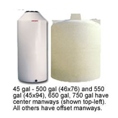
- Vertical cylindrical tanks with flat bottoms. The simplest geometry: volume is approximately level times cross-sectional area, with minor non-linearity at the bottom from the bottom dome curvature. Any transmitter type is suitable; the conversion is essentially linear. Reference N-40164 5000 gallon Norwesco vertical and N-43128 10,000 gallon Norwesco vertical for the bulk-vertical envelope.
- Horizontal cylindrical tanks. The volume-vs-level relationship is non-linear (small at low and high levels, larger at mid-level due to the changing cross-section). The transmitter electronics or the SCADA layer applies a strapping table or mathematical conversion to translate level to volume. Verification protocols have to compare against the volume conversion rather than just the level.
- Cone bottom tanks. The bottom cone introduces additional non-linearity at low levels. The volume conversion includes the cone geometry; the transmitter dip-tape verification has to account for the cone in the level-to-volume calculation. Reference N-42064 15 gallon cone bottom for the cone-bottom envelope.
- Doorway-shaped or non-symmetric tanks. Specialty tank shapes have custom volume-vs-level relationships that must be characterized at commissioning. Reference N-44800 100 gallon doorway tank for the specialty-shape envelope.
- Loaf or portable tanks. Portable tanks may have rounded shapes complicating level conversion. Reference N-45345 100 gallon loaf.
The transmitter installation engineering accounts for the geometry; the verification protocol uses the same geometric conversion. List pricing on each product page; LTL freight to your ZIP via the freight estimator or by phone at 866-418-1777.
8. The Calibration Records and Documentation
The calibration program produces records that support the inventory accuracy program and any regulatory reporting:
- Per-transmitter calibration log. Every calibration event logged with date, technician, reference method used, before-correction reading, after-correction reading, and any remedial action. The log is the per-transmitter history that informs interval planning and replacement timing.
- Reference equipment traceability. The dip tape, calibrated flow meter, or pressure source used as the reference has its own calibration traceability to the national measurement standard. The traceability chain documents the chain of references back to the SI definition of the relevant measurement.
- Annual program review. Annual aggregate review of the calibration program: number of calibrations performed, drift detected, corrective actions taken, replacements completed, and overall program effectiveness. The review identifies systemic issues (e.g., a particular transmitter type drifting more than expected) and informs the next-year program.
- Regulatory reporting where applicable. Some regulated industries (pharmaceutical, food, environmental) require calibration documentation as part of regulatory inspection. The program records meet the regulatory documentation standard for the applicable industry.
The records are an operational asset and a regulatory requirement. The site that maintains comprehensive records demonstrates the calibration program's effectiveness; the site that does not has to reconstruct history at every reconciliation discrepancy investigation.
9. The Calibration Engineering Conclusion
Tank-mounted level transmitters drift. Each type drifts via its own mechanisms at its own rate, and the cumulative drift over un-recalibrated service produces measurable inventory accuracy errors. The drift-aware program detects drift early through scheduled verification using calibrated reference methods, applies corrective action (re-zero, re-span, repair, or replace) before the drift propagates into significant inventory accuracy errors, and documents the calibration history for inventory reconciliation and regulatory purposes.
The service-interval planning balances drift risk against verification cost. Cleaner service and more accurate transmitter types have longer intervals; chemistry-impacted service and less stable transmitter types have shorter intervals. The condition-based approach adjusts the interval per transmitter based on observed drift history rather than applying a uniform calendar across all assets.
OneSource Plastics ships polyethylene tanks across 5 brands — Norwesco, Snyder, Chem-Tainer, Enduraplas, Bushman — with the manufacturer-published dimensional specifications that the level-measurement geometry uses. The transmitter selection, installation, and calibration program is operations engineering at the customer site; the tank's geometric characteristics are documented in the manufacturer drawings that the calibration team uses for level-to-volume conversion. List pricing on each product page; LTL freight to your ZIP via the freight estimator or by phone at 866-418-1777. For related operations engineering see secondary containment requirements and tank specification sheet reading.
Recommended Tanks for This Guide
Live pricing, updated automatically · estimate freight to your ZIP.