Belt-Driven Mixer Integration on Polyethylene Bulk Tank Tops: Torque Rating Math, Mounting Strategies That Do Not Transmit Reaction Loads to the Tank Dome, and Seal Selection That Survives Continuous Service


The belt-driven mixer that gets bolted onto a polyethylene tank top is the most common recipe for a cracked dome and a destroyed mixer in the bulk-storage industry. The mixer itself is usually a serviceable piece of process equipment. The mounting bracket that connects it to the tank top is too often a flat plate of steel bolted through the tank dome with sealant and a hope that the polyethylene will not yield under the dynamic torque loads. It usually does yield. The result is a dome that progressively deforms, a mixer shaft that wanders out of vertical alignment, a belt that walks off the pulleys, and eventually a seal that fails and leaks the tank contents around the shaft.
This article walks the engineering of belt-driven mixer integration on polyethylene tank tops. The references are the manufacturer technical bulletins from Norwesco, Snyder, Chem-Tainer, Enduraplas, and Bushman on tank-top fitting load ratings, ASTM D1998 (polyethylene upright storage tanks), ANSI/HI 9.6 (rotodynamic pumps and equivalent for mixer reaction-load engineering), and the mixer-manufacturer reference data from Chemineer, Lightnin, Philadelphia Mixing Solutions, and similar suppliers on top-mount loading and shaft-deflection tolerances. The objective is the field-installable mixer mount that absorbs reaction torque and shaft loads through an independent bridge structure, leaving the polyethylene tank in its actual structural role.
1. Why Belt-Driven Mixers Stress Tanks Differently Than Direct-Drive Units
The direct-drive mixer mounted on a tank top transmits a relatively predictable steady-state torque to the mounting plate. The torque is the motor torque divided by any gear-reduction ratio, applied to a shaft running at constant RPM in nominally constant-density fluid. A 5-horsepower direct-drive mixer at 100 RPM transmits roughly 263 inch-pounds of steady-state torque to the mount. The peak transient torque during start-up or upset conditions is typically 2-3x the steady-state — substantial but bounded.
The belt-driven mixer is a different load case. The belt-and-pulley assembly introduces additional dynamic complexity:
- Belt tension as a constant lateral load on the shaft and bearings, which adds a transverse force that the steady-state torque does not include. A typical V-belt installation transfers 50-200 pounds of belt-tension lateral load through the input pulley to the bearing housing.
- Pulley-eccentricity-induced vibration, which adds a cyclic load at the rotational frequency that the bearings and the mounting structure must absorb. Even a precision-balanced pulley assembly imposes a few pounds of cyclic load; a worn or improperly aligned assembly can impose tens of pounds at frequencies that may approach the natural frequency of the tank dome.
- Belt-jump and belt-slip events that briefly remove the load from the shaft, then re-impose it as the belt re-engages. The transient torque during a belt-slip recovery can spike well above the steady-state.
- Misalignment between the motor pulley and the shaft pulley that creates an axial force component on the bearing as the belt tries to track. A 1-degree misalignment at modest belt tension imposes a few pounds of axial load; a 3-degree misalignment imposes substantially more and is the leading cause of premature bearing failure on belt-driven equipment.
The polyethylene tank dome was not designed for any of these dynamic loads. The dome is designed for the static fluid pressure of the tank contents and the modest distributed load of personnel walking on top during inspection. The cyclic and transient loads imposed by a belt-driven mixer mounted directly on the dome accumulate as fatigue damage in the polyethylene, eventually appearing as cracks radiating from the mounting bolts.
2. Torque Rating Math for the Mounting Structure
The first calculation in any belt-driven mixer mount is the steady-state and peak torque envelope. The mount must absorb the steady-state torque plus a substantial safety factor for transients without yielding the structural members or the connection to the tank.
- Steady-state shaft torque (inch-pounds) = (5252 × motor horsepower) / shaft RPM. A 7.5-horsepower motor driving the shaft at 80 RPM delivers 492 inch-pounds steady-state.
- Peak start-up torque is typically 2-3x steady-state for fluid-shear-dominated mixing, rising to 4-5x for high-viscosity fluid where the shaft must overcome breakaway from a settled state.
- Belt-side transient at slip recovery can spike to 3-4x steady-state instantaneously, imposing an impulsive load that the structure must absorb without yielding.
- Reaction torque on the mount is equal and opposite to the shaft torque. The mount must transmit this reaction torque from the mixer body to the structural support without rotating the entire assembly, which means the mount-to-support connection must develop the moment.
The mounting bridge structure is sized for the worst-case peak torque with a safety factor of 4 (industry-standard for overhung loads in process equipment). For the 7.5-horsepower 80-RPM example, the design torque becomes 492 × 4 × 4 = 7,872 inch-pounds for the start-up case, or 492 × 3 × 4 = 5,904 inch-pounds for the slip-recovery case. The bridge structure and connection bolts are sized to develop this moment with concrete-anchored or floor-anchored support points; the polyethylene tank is not a load-carrying member in the calculation.
3. The Independent Bridge-Mount Approach
The clean engineering solution for belt-driven mixer mounting is an independent bridge structure that spans across the tank top and supports the mixer without imposing the dynamic loads on the dome. The bridge legs extend down the sides of the tank to anchor points on the foundation pad, the secondary containment dike, or a freestanding floor frame.
The engineering elements:
- Bridge structure of welded steel I-beam, channel, or HSS sized for the peak torque envelope. Typical specifications use W6x12 or C6x10.5 sections for tank diameters up to 8 feet, scaling up for larger tanks. The detailed design is by a structural engineer with the mixer manufacturer's reaction-load specification.
- Mixer mounting flange welded to the bridge top, drilled and tapped for the mixer manufacturer's specified bolt pattern. The flange thickness is typically 3/4 inch minimum to develop the bolt-circle moment without distortion.
- Bridge legs anchored at four corners around the tank perimeter, with each leg supported on its own concrete pier or anchored to the secondary containment slab. The legs are positioned so the bridge does not bear weight on the tank top under any operating condition.
- Lateral stability ties to the tank only as a stability element, not as a structural support. The tank may serve as a sway-brace point but never as a load-bearing element. The ties are designed with sufficient compliance to allow tank thermal expansion without transmitting stress.
- Clearance maintained between the bridge underside and the tank dome of at least 4 inches. The clearance accommodates tank shell flexure under fluid load, freeze expansion, and any transient deformation, ensuring the bridge never bears weight on the dome.
The bridge approach requires more steel and more engineering than the through-bolt-the-dome approach. It also delivers a mixer installation that runs for 20+ years without progressively damaging the tank.
4. Shaft Seal Selection for Tank-Top Penetration
The mixer shaft enters the tank through a penetration in the dome. The seal at this penetration must accommodate the shaft rotation while preventing fluid loss, vapor escape, and atmospheric contamination of the tank contents. The seal selection depends on the chemistry, the operating temperature, the rotational speed, and the regulatory environment.
- Lip seals (single or double) for benign chemistry water and aqueous-solution service: economical, easy to replace, and tolerant of modest shaft runout. Single lip is rated for atmospheric-pressure service; double lip provides a small pressurized buffer chamber that can be monitored for leakage. Material selection (FKM, EPDM, NBR) follows the same chemistry-compatibility logic as elsewhere in the system.
- Mechanical seals (single, double, or tandem) for hazardous chemistry, high-purity, or vapor-sensitive service: the standard for process applications where lip seals are inadequate. Single mechanical seals serve atmospheric-pressure non-volatile service; double mechanical seals with a barrier-fluid system handle volatile, toxic, or hazardous chemistry where any leak is unacceptable.
- Stuffing boxes with packing for legacy installations or specialized service: serviceable, repairable in place, but require periodic adjustment and contribute a continuous slow leak rate that may be unacceptable for modern installations. Used primarily where seal materials cannot be sourced for unusual chemistry envelopes.
- Magnetic drive coupling instead of a shaft penetration: the seal-less alternative where the motor torque is transmitted through a magnetic coupling across an unbroken tank wall. Eliminates the shaft seal entirely; cost is higher and the torque-transmission limit is lower than a direct-drive shaft.
The default specification for benign-water mixing on outdoor agricultural and municipal water tanks is a single lip seal in FKM or NBR. The default for hazardous-chemistry mixing is a double mechanical seal with a barrier fluid that is more compatible than the process fluid (so any seal failure leaks barrier fluid into the tank, never the reverse). The detailed selection is from the seal manufacturer's compatibility chart for the specific chemistry and operating temperature.
5. Vibration and Resonance — The Hidden Failure Mode
The polyethylene tank has a natural frequency that depends on the geometry, the wall thickness, and the contained fluid. For typical vertical bulk tanks, the dome and upper-shell natural frequencies are in the 5-30 Hz range, which overlaps with the rotational frequencies of belt-driven mixer pulleys at common operating speeds. If the mixer rotational frequency, the belt-passage frequency, or any harmonic of either coincides with the tank natural frequency, the resulting resonance amplifies the vibration loads by 5-20x.
The resonance failure mode shows up as accelerated fatigue cracking around the mixer mount, fitting bosses on the tank top, and the tank-shell-to-dome weld line. The crack growth rate under resonance loading can be 10-50x the rate under non-resonant operation. A mixer installed at a coincidentally-resonant speed can crack a tank dome within months; the same mixer at a slightly different speed runs indefinitely.
The engineering remedy:
- Vibration analysis at commissioning using accelerometers on the mixer body, the bridge structure, and the tank dome. The frequency-response data identifies any resonance peaks and the operating speeds that excite them.
- Operating-speed selection that avoids the resonance bands by at least 10 percent in either direction. If the analysis identifies a resonance at 24 Hz, the operating frequency should stay below 22 Hz or above 26.5 Hz.
- Vibration isolation between the bridge and the mixer body when the mixer reaction-load envelope cannot be entirely de-coupled from the tank. Engineered elastomer isolators reduce the transmitted force but introduce their own dynamic envelope that must be analyzed.
- Periodic re-verification as the equipment ages. Bearing wear, belt stretch, and shaft eccentricity all shift the vibration envelope; a system that was clean at commissioning may develop resonance over years of service.
The vibration analysis is a few thousand dollars at commissioning. The cost of replacing a resonance-cracked tank is the entire tank price plus the installation labor plus the production downtime — substantially higher than the analysis cost.
6. The Tank Selection That Accommodates Top-Mount Mixing
The tank selection for a belt-driven mixer installation should consider the dome geometry, the structural envelope around the mounting points, and the manufacturer's published top-load ratings. Norwesco, Snyder, Chem-Tainer, Enduraplas, and Bushman each publish technical guidance for top-mount equipment installations.
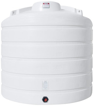
- Vertical bulk tanks with reinforced dome construction for top-mount equipment: reference N-40164 5,000 gallon Norwesco vertical and N-43128 10,000 gallon Norwesco vertical for the bulk-storage end of the catalog. The XLPE construction provides the wall thickness for the structural ties and lateral stability connections.
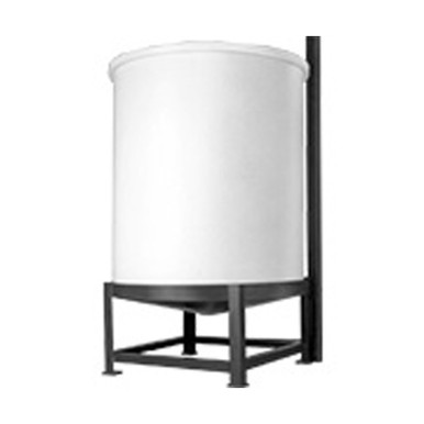
- Cone-bottom tanks where mixing is essential to maintain suspension: reference N-43852 1,000 gallon 45-degree cone; the cone geometry combined with a properly-engineered bridge mount delivers efficient suspension mixing for slurries and high-solids service.
- Smaller cone-bottom inductor tanks for batch mixing operations: reference N-42064 15 gallon 57-degree cone bottom inductor for the laboratory and small-batch end where the mixer is sized for low-power benchtop operation. The mounting strategy still applies; the bridge is just smaller.
- Snyder Captor double-wall units for hazardous-chemistry mixing: reference the SII-1006600N42 10,000 gallon XLPE Captor for installations where the mixing operation is chemistry-sensitive and the integrated containment provides the redundancy that the seal system alone may not.
The procurement conversation should include the planned mixer specification, the mounting strategy, the seal selection, and the vibration-analysis budget at the same time the tank is specified. Retrofitting a properly-engineered bridge to an existing installation is materially more expensive than designing the system as a whole at the original installation.
7. The Inspection and Maintenance Cadence
The belt-driven mixer installation has more wear elements than a direct-drive unit and correspondingly requires a more attentive maintenance regime:
- Weekly visual inspection. Verify belt condition, pulley alignment, mixer noise envelope, and any visible leakage at the shaft seal.
- Monthly belt tension and alignment check. Belt tension drifts as the belt stretches and as the mounting structure settles. Re-tension to manufacturer specification and re-verify pulley alignment with a straight-edge or laser tool.
- Quarterly bearing condition assessment. Vibration analysis or temperature measurement on the bearing housings detects wear before failure. A bearing running 20 F above its baseline temperature is approaching the end of its service life.
- Annual seal inspection and replacement-as-needed. Lip seals are typically replaced annually as preventive maintenance; mechanical seals are inspected annually with replacement based on condition. Stuffing-box packing is adjusted at every annual inspection and replaced every 2-3 years.
- Five-year detailed structural inspection. The bridge mount, the anchor connections, and the tank-side stability ties get a detailed inspection. Re-verify the vibration envelope; aged bearings and worn pulleys may have shifted the resonance characteristics.
The maintenance cadence applies regardless of whether the mixer is running continuously or intermittently. Intermittent service often accelerates the wear because each start cycle imposes the peak transient torque and each stop allows condensation and corrosion to develop in components that would stay dry under continuous operation.
8. The Engineering Discipline Conclusion
The belt-driven mixer is a serviceable piece of process equipment; the integration onto a polyethylene tank top is the engineering problem that gets solved poorly more often than it gets solved well. The recipe for the cracked dome is the flat plate of steel bolted through the polyethylene with a sealant gasket and a hope. The recipe for the 20-year installation is the independent bridge structure that absorbs the dynamic loads, the engineered seal selection that matches the chemistry and the regulatory environment, and the vibration analysis that confirms the operating speed avoids the tank natural frequencies.
The cost difference between the two installations is a few thousand dollars in steel and engineering. The cost difference in outcomes is a multi-year service life versus a multi-month service life. The math favors the engineering, just as it does for every other piece of the tank-installation envelope.
OneSource Plastics ships the polyethylene tank platform that is the foundation of these mixer installations across all 5 brands — Norwesco, Snyder, Chem-Tainer, Enduraplas, Bushman — with dome construction documentation, top-fitting load ratings, and dimensional drawings that the structural engineer needs to design the bridge mount around. List pricing by SKU is on the product page; LTL freight to your ZIP is quoted separately via the freight estimator or by phone at 866-418-1777. For related installation engineering see tank mixer and agitator engineering and tank piping support engineering.
Recommended Tanks for This Guide
Live pricing, updated automatically · estimate freight to your ZIP.