Liquid Level Switch Redundancy on Polyethylene Tanks: Float Switch Versus Conductive Probe Versus Ultrasonic Versus Capacitance Comparison and the Two-of-Three Voting Architecture for High-Consequence Tank Service


The liquid level switch on a chemistry storage tank serves several control functions: it triggers high-level alarms that protect against overfill during fill operations, low-level alarms that protect downstream pumps from cavitation when the tank approaches empty, and intermediate setpoints that drive automatic fill, transfer, and process control logic. A single level switch handling all these functions is a single point of failure: when the switch fails undetected the protection function disappears and the consequence (tank overfill, pump damage, process upset) develops without warning. High-consequence tank service therefore uses redundant level switches, often of dissimilar technology types, in voting architectures that detect any single-switch failure and continue protecting the tank.
This article compares the four common level switch technologies (float, conductive probe, ultrasonic, capacitance), their failure modes, and the two-of-three voting architectures that build dependable tank-level protection from independent switch instances. The discussion is grounded in instrument engineering practice, manufacturer fitting compatibility across the 5-brand catalog of Norwesco, Snyder, Chem-Tainer, Enduraplas, and Bushman, and chemistry-service installation experience. List pricing on each tank product page; LTL freight quoted to your ZIP via the freight estimator or by phone at 866-418-1777.
1. The Single-Switch Failure Problem
A single level switch handling tank protection functions exposes the operator to several failure scenarios:
- The undetected stuck switch. A float switch with a corroded pivot, a conductive probe with deposit buildup on the electrodes, an ultrasonic head with film accumulation, or a capacitance probe with insulator coating can stick at one indication state and fail to change output when the actual liquid level moves. The control system reads the stuck output as accurate and acts accordingly. The tank fills past high-high alarm without alarm, or empties past low-low alarm without alarm.
- The intermittent contact failure. A switch with intermittent electrical contact (loose terminal, partial wire break, weak relay coil) toggles between correct and incorrect output. The control system sees the toggling and, depending on logic, either filters it out (missing real alarms) or amplifies it (false alarms). Either failure mode produces operational disruption.
- The bias drift. An analog level transmitter (ultrasonic or capacitance with continuous output) can drift its calibration over time, producing readings that shift away from the true level. A 5-10 percent drift moves the alarm setpoints accordingly and the protection threshold becomes uncertain.
- The catastrophic failure. A switch can fail completely (no output, locked at upper or lower bound, total loss of communication). Modern control systems detect total failure and raise an instrument fault alarm. The detection of total failure is reliable; the difficult cases are the partial failures above.
- The maintenance-induced failure. A switch that was working before maintenance can be returned to service mis-installed (wrong polarity, loose connection, mis-positioned float, mis-calibrated transmitter). The maintenance-induced failure may not be detected until the next protection event.
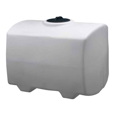
- Reference tank for level instrumentation. Reference N-40164 5000 gallon Norwesco vertical as the typical chemistry-service tank where multi-switch level instrumentation is justified. The 5000 gallon class typically carries hypochlorite, peroxide, or specialty chemistry where overfill or run-dry is a high-consequence event.
The single-switch failure problem motivates the redundant architecture. The cost of redundant switches and voting logic is small compared to the consequence of an undetected protection failure on high-value chemistry or critical process equipment.
2. Float Switch Technology Profile
The float switch is the simplest and most common level instrument:
- The mechanism. A buoyant float on the chemistry surface activates a switch (mechanical, magnetic reed, or hall-effect) when the float rises or falls past a setpoint. The setpoint can be the float arm position (cantilever float), the float vertical position (vertical-rod float), or the float horizontal position (side-mount float). The output is typically a single-point switch contact.
- Strengths. Float switches are simple, low-cost ($50-$300 per unit), widely available in chemistry-compatible materials (PP, PVDF, stainless), and tolerant of dirty chemistries that would foul electrical sensors. The technology has been in industrial service for decades with well-understood failure modes.
- Weaknesses. Float switches have moving parts that can stick, freeze, or accumulate debris. The float buoyancy depends on chemistry specific gravity; a chemistry change of 10-20 percent in specific gravity shifts the float position. Floats can corrode internally if seal integrity fails. Dual-float assemblies (high alarm and low alarm in one fitting) cost more and add complexity but use only one tank fitting.
- Failure modes. Stuck float (mechanical jam, debris, corrosion), broken float (hydrocarbon swell or chemistry attack), failed switch contacts (contact corrosion or fatigue), broken stem (mechanical damage from mixing or recirculation), waterlogged float (seal failure leading to sinking).
- Tank fitting integration. Float switches install through a dedicated tank-top fitting (typically 1.5 inch or 2 inch threaded boss) or through a side-mount fitting at the alarm setpoint elevation. Side-mount floats are simpler to install and inspect but require a tank-wall penetration at the alarm height. Top-mount floats use a single tank-top fitting but require longer probe assemblies.
- Chemistry compatibility considerations. The float housing material, the stem material, the mounting fitting material, and the cable jacket material all must be compatible with the chemistry. Hypochlorite tanks use PP or PVDF; ammonia tanks use 316L stainless or PVDF; peroxide tanks use 304/316L stainless with passivated surface. The chemistry-compatibility check is performed across all four float components.
The float switch is the workhorse level instrument. It is the right choice for many applications and serves well in redundant architectures alongside dissimilar technologies.
3. Conductive Probe Technology Profile
The conductive probe is the second common level instrument:
- The mechanism. A pair of electrodes (or a single electrode and a tank ground reference) detects the presence of conductive liquid at the electrode tip elevation. When the chemistry rises to the electrode tip the circuit closes; when it falls below the electrode tip the circuit opens. Multiple electrodes at different elevations give multiple level setpoints from a single probe assembly.
- Strengths. Conductive probes have no moving parts and no chemistry-density dependence. Multiple setpoints (high, intermediate, low) come from a single tank fitting. Cost is $200-$800 for a multi-electrode probe with associated relay. The electronics are simple and rugged.
- Weaknesses. Conductive probes only work on conductive chemistry (water, ammonia, hypochlorite, brine). Non-conductive chemistry (hydrocarbons, glycols, deionized water) is invisible to the probe. The electrodes must be reasonably clean; deposits and biofilm shift the apparent level. False alarms occur from conductive condensate forming on the electrodes during low-humidity conditions.
- Failure modes. Coated electrodes (deposit buildup obscuring electrode tip), broken electrode (corrosion or mechanical damage), failed relay (electrical contact wear or electronic failure), false alarm from condensate (humidity bridging across electrodes), shorted electrode (contact between adjacent electrodes from debris or mechanical damage).
- Tank fitting integration. Conductive probes install through a tank-top fitting (1.5 inch or 2 inch threaded boss, occasionally larger for multi-electrode assemblies). The probe extends down into the chemistry from the tank top. The cable exits through the same fitting and runs to the relay enclosure.
- Chemistry compatibility considerations. The probe sheath material, the electrode tip material, the cable, and the head enclosure all must be chemistry-compatible. PVDF sheath with 316 stainless or Hastelloy electrode tips covers most chemistry-service applications. The conductivity of the chemistry must be verified at expected operating range; very low conductivity chemistry (deionized water) needs different technology.
The conductive probe is the right choice for conductive chemistries with multiple setpoints from a single fitting. It serves as a dissimilar-technology partner to float switches in redundant architectures.
4. Ultrasonic Level Technology Profile
The ultrasonic level transmitter is the first of the analog non-contact technologies:
- The mechanism. An ultrasonic transducer mounted at the tank top emits a sound pulse downward toward the chemistry surface; the pulse reflects from the surface and returns to the transducer. The time-of-flight measurement, divided by the speed of sound in the headspace gas, yields the distance from the transducer to the chemistry surface. The level is calculated as the tank height minus the distance.
- Strengths. Non-contact (no chemistry exposure of the transducer), continuous level output (4-20 mA or digital protocol), suitable for many chemistries regardless of conductivity. The output supports any number of setpoints in software, including high, low, intermediate, and rate-of-change calculations.
- Weaknesses. The speed of sound depends on headspace gas composition and temperature; ammonia vapor or organic solvent vapor in the headspace alter the calibration. Foam or vortex on the chemistry surface scatters the return pulse and produces unstable readings. Condensation on the transducer face attenuates the signal. Cost is $1,000-$3,000 per transmitter.
- Failure modes. Calibration drift from headspace gas composition change, foam-induced reading instability, condensate-induced signal attenuation, transducer face fouling, electronic failure, mounting instability from vibration.
- Tank fitting integration. Ultrasonic transmitters install at the tank top with a clear sight path down to the chemistry surface. The fitting is typically a 4-inch or 6-inch flanged stand-off boss to provide adequate beam-spread clearance. The fitting must be on the tank centerline or in a position that does not see standing waves from inlet flow.
- Chemistry compatibility considerations. The transducer face is in vapor contact only; the materials are typically PVDF, PP, or stainless. The compatibility check is for the headspace vapor rather than the liquid chemistry. Aggressive vapor (chlorine, ammonia at high concentration, fluoride compounds) requires premium materials.
The ultrasonic transmitter provides continuous level data and integrates well with modern control systems. It is the typical primary technology in chemistry-service tanks where continuous level data drives process control.
5. Capacitance Level Technology Profile
The capacitance level transmitter is the second analog technology:
- The mechanism. A capacitance probe extends from the tank top into the chemistry, with the tank wall (grounded) or a reference electrode forming the second capacitor plate. The capacitance varies with the dielectric constant of the medium between the plates; chemistry has a much higher dielectric constant than vapor, so the capacitance increases as the chemistry rises along the probe.
- Strengths. Continuous level output regardless of foam, vortex, or vapor composition. Works on conductive and non-conductive chemistry (with appropriate probe configuration). No moving parts. Cost is $800-$2,500 per transmitter.
- Weaknesses. Calibration depends on chemistry dielectric constant; chemistry composition changes shift the calibration. Coating buildup on the probe shifts the measurement (the probe coating becomes part of the capacitor). Probe length must match tank height closely.
- Failure modes. Coating-induced calibration drift (the most common failure), probe insulation breakdown (chemistry attack or aging), broken probe (mechanical damage from mixing), electronic failure, calibration drift from chemistry composition change.
- Tank fitting integration. Capacitance probes install through a tank-top fitting (typically 1.5 inch or 2 inch threaded boss, larger for longer probes). The probe extends down through the chemistry to near the tank bottom. The cable exits through the same fitting.
- Chemistry compatibility considerations. The probe sheath and tip materials must be chemistry-compatible. PFA-coated stainless probes cover aggressive chemistry service. The probe insulation must hold the rated dielectric integrity across the chemistry exposure.
The capacitance probe is the dissimilar-technology partner to ultrasonic in many premium tank installations. The two together cover the failure modes of either technology alone.
6. The Two-of-Three Voting Architecture
The voting architecture combines three independent switches into a redundant protection system:
- The voting principle. Three switches at the same setpoint elevation each independently report the level state (above setpoint or below). The control system requires at least two of the three switches to agree before acting on the level state. A single-switch disagreement (the failed switch) does not trigger action and raises an instrument-fault alarm.
- The dissimilar-technology requirement. The three switches should use dissimilar technologies (for example: one float, one conductive probe, one ultrasonic) to avoid common-cause failure. A coating buildup that affects the conductive probe does not affect the float; a foam condition that affects the ultrasonic does not affect the float; a chemistry-density change that affects the float does not affect the ultrasonic. Dissimilar technologies eliminate the failure mode where all three switches fail from the same cause.
- The setpoint alignment. All three switches are calibrated to the same alarm setpoint elevation. Calibration error in one switch shifts that switch's transition slightly off the others; the voting logic accommodates small offsets but large offsets produce false instrument-fault alarms.
- The instrument-fault alarm logic. When the three switches disagree (one indicates above, two indicate below), the voting logic acts on the majority but raises an instrument-fault alarm pointing operators to the disagreeing switch. The operator investigates and either corrects the failed switch or accepts the operation under the remaining two with reduced redundancy.
- The high-high and low-low duplication. The high-high alarm setpoint and the low-low alarm setpoint each get their own three-switch voting array. A 5000 gallon chemistry tank with high and low protection thus carries six level switches plus possibly an analog transmitter for continuous monitoring. The fitting count and instrument cost is substantial but matches the consequence of failure on high-value chemistry.
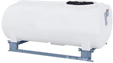
- Reference tank for redundant level instrumentation. Reference N-41524 2500 gallon Norwesco as a smaller chemistry-service tank where the redundant architecture might be simplified to two switches (a primary float plus a secondary conductive probe) at high alarm and a single low alarm float, with the instrumentation cost matched to the smaller tank value.
The two-of-three voting architecture is the standard for high-consequence chemistry tank protection. Lower-consequence applications use simpler architectures (single switch or two-of-two with fault detection) but the principle of dissimilar technologies for redundancy applies across the range.
7. Calibration, Testing, and Maintenance Cadence
The level switch reliability depends on disciplined calibration and testing:
- Initial commissioning verification. At commissioning each switch is verified by physical level change in the tank: pump in chemistry to cross the alarm setpoint and confirm the switch transitions; pump out chemistry to cross back and confirm the reverse transition. The verification establishes the as-installed calibration.
- Quarterly bump test. Quarterly the switches are exercised through their alarm setpoints (by physical level change or by simulation through transmitter calibration mode for analog instruments). The bump test confirms each switch still transitions at the correct setpoint. Drift or failure is caught at the bump test rather than during a real protection event.
- Annual full calibration. Annually each transmitter (analog instruments) is fully recalibrated to factory specification with calibration documentation in the maintenance record. Float and conductive switches are inspected for mechanical condition, cleaned, and re-installed.
- 5-year overhaul. Every 5 years the level instruments are removed, fully inspected, replaced as needed, and re-installed with new gaskets and connections. The 5-year overhaul aligns with typical service-life expectations for level instruments.
- The maintenance log discipline. Every action on a level switch is logged: bump test result, calibration values, replacement of parts, observations of condition. The log establishes the trend across years and supports root-cause investigation when a failure occurs.
- The post-maintenance verification. Every maintenance event ends with a post-maintenance verification: the same bump test that the quarterly schedule uses, performed immediately after maintenance, confirms the switch is operational before returning to protective service.
The calibration, testing, and maintenance cadence is the operational discipline that keeps the redundant architecture redundant. Three switches that have all drifted out of calibration provide no real protection regardless of voting logic.
8. The Level Switch Redundancy Conclusion
Liquid level switch redundancy on high-consequence polyethylene tanks combines dissimilar-technology switches in voting architectures that detect single-switch failure and continue protecting the tank. The four common technologies (float, conductive probe, ultrasonic, capacitance) each have specific strengths, weaknesses, and failure modes; the right combination of two or three technologies covers each others' failure modes and produces a dependable level protection system. The maintenance discipline (quarterly bump test, annual calibration, 5-year overhaul, log discipline) is essential to keeping the architecture functional across the service life.
OneSource Plastics ships polyethylene tanks across the 5-brand catalog (Norwesco, Snyder, Chem-Tainer, Enduraplas, Bushman) with manufacturer-published fitting specifications that accommodate the level instrument range described here. The instrument selection and integration is performed by the customer site engineer with reference to the chemistry, the consequence of failure, and the budget for instrumentation. List pricing on each product page; LTL freight to your ZIP via the freight estimator or by phone at 866-418-1777. For related instrumentation and protection engineering see vent sizing math and fitting and bulkhead sizing.
Recommended Tanks for This Guide
Live pricing, updated automatically · estimate freight to your ZIP.