Variable-Speed Drive Sizing for Tank-Fed Pumps With Diurnal Demand Cycling: Affinity Law Math, Carrier-Frequency Selection, Motor De-Rating Across the Speed Range, and the Energy-Recovery Economics That Pay for the Drive Within 18 Months


The traditional approach to tank-discharge pumping uses a fixed-speed motor with a throttle valve or a recirculation loop to match flow to demand. The approach wastes energy: pumping at full speed against a partially closed valve dissipates the difference as heat in the valve and bypass loop. A variable-speed drive (VFD) on the same pump motor matches pump speed to the actual demand, reducing energy consumption substantially across the demand cycle. For tank-fed pumps with diurnal demand patterns (high during day shifts, low overnight) the VFD energy savings typically pay for the drive installation within 12 to 24 months. This article walks the affinity law math, the drive sizing methodology, motor compatibility considerations, and the procurement and installation discipline that produces a successful VFD-on-pump installation.
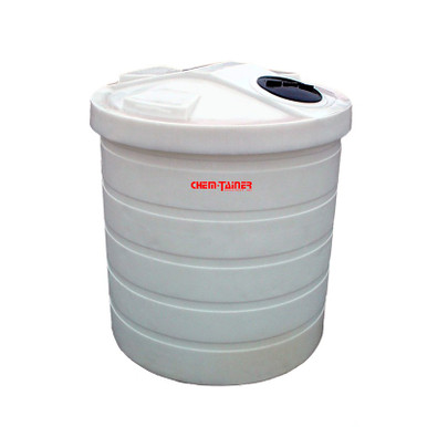
The discussion is grounded in pump and electric motor engineering, NEMA and IEC drive standards, and field practice for tank discharge pumping across the 5-brand polyethylene tank catalog (Norwesco, Snyder, Chem-Tainer, Enduraplas, Bushman). List pricing on each tank product page; LTL freight quoted to your ZIP via the freight estimator or by phone at 866-418-1777.
1. The Affinity Law Math for Pump Speed Reduction
The affinity laws describe the relationship between pump speed, flow, head, and power for a centrifugal pump:
- Flow scales linearly with speed. Flow rate Q is proportional to pump rotational speed N. Reducing pump speed from 100 percent to 50 percent reduces flow rate from 100 percent to 50 percent. The first affinity law: Q1/Q2 = N1/N2.
- Head scales as the square of speed. Pump head H is proportional to the square of the speed. Reducing pump speed from 100 percent to 50 percent reduces head from 100 percent to 25 percent. The second affinity law: H1/H2 = (N1/N2)^2.
- Power scales as the cube of speed. Pump shaft power P is proportional to the cube of the speed. Reducing pump speed from 100 percent to 50 percent reduces power from 100 percent to 12.5 percent. The third affinity law: P1/P2 = (N1/N2)^3.
- The cubic relationship as the savings driver. The cubic power scaling is the source of the VFD energy savings. A pump operating at 75 percent of rated speed consumes only 42 percent of rated power; at 50 percent speed it consumes 12.5 percent. The savings on demand cycles where the pump operates below rated speed for substantial fractions of the day are dramatic.
- System curve interaction with affinity laws. The system curve (head versus flow on the discharge piping) intersects the pump curve at the operating point. As pump speed reduces, the pump curve shifts down and to the left, and the operating point moves to lower flow and lower head. The new operating point depends on the system curve shape: a system with high static head (lifting fluid) versus a system with all-friction head (recirculation) produces different VFD savings curves.
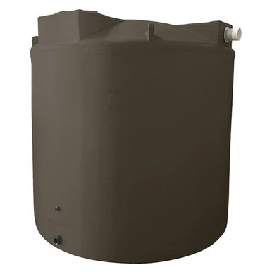
- Reference tank for typical pumping math. Reference N-40164 5000 gallon Norwesco vertical with a 5 HP discharge pump rated 50 GPM at 60 feet head. Reducing pump speed to 75 percent gives 37.5 GPM at 33.75 feet head with shaft power of 2.1 HP (down from 5 HP at full speed); the energy savings at 75 percent speed approach 60 percent.
The affinity laws are the mathematical foundation of VFD pump-control engineering. Every sizing decision and every savings calculation references back to these three relationships.
2. Sizing the VFD for the Pump Motor
The VFD selection for a tank-fed pump motor is driven by motor power, motor type, and operational profile:
- VFD horsepower rating. The VFD rating must equal or exceed the motor nameplate horsepower. A 5 HP motor requires a 5 HP or larger VFD. Common practice is to size the VFD to the next standard size above the motor rating to allow for future motor upgrades or for service factor margin. A 5 HP motor with a 7.5 HP VFD provides 50 percent service factor margin.
- VFD voltage compatibility. The VFD input voltage must match the available service voltage (240V single-phase, 480V three-phase, 600V three-phase typical for North American industrial sites). The VFD output voltage must match the motor nameplate (typically the same as input voltage but some VFDs provide voltage step-up or step-down). Mismatched voltages require transformers in addition to the VFD.
- VFD current rating including service factor. The VFD output current rating must accommodate the motor full-load amperage plus any service factor margin. NEC table 430.250 provides motor full-load amperage for standard motors; the VFD should be sized to 110-125 percent of FLA. For a 5 HP three-phase 460V motor (FLA = 7.6 amps per NEC), the VFD output should be rated at 9-10 amps minimum.
- Carrier frequency selection. The VFD output is a pulse-width-modulated waveform with a carrier frequency typically in the 1-16 kHz range. Lower carrier frequencies produce higher motor noise but lower VFD heat and longer cable run capability. Higher carrier frequencies produce quieter motor operation but more VFD heat and shorter cable limits. Default settings are typically 4-6 kHz; tank-pump installations rarely require deviation.
- Variable-torque versus constant-torque rating. VFDs are rated for variable-torque (VT) or constant-torque (CT) duty. Centrifugal pumps follow VT loading (torque drops as the square of speed); VT-rated drives are appropriate. Positive displacement pumps follow CT loading and require CT-rated drives. Most tank-discharge applications use centrifugal pumps and VT drives.
- Reference 1000 gallon for typical small-pump VFD application. Reference N-40152 1000 gallon Norwesco vertical with a 1 HP discharge pump as a typical small VFD application. The 1 HP motor with a 1.5 HP variable-torque VFD at 240V three-phase costs approximately 600-1000 dollars for the VFD and 100-200 dollars for the installation labor.
The VFD sizing follows established rules and is straightforward for standard pump applications. The non-standard cases (high inertia loads, high starting torque requirements, voltage mismatches) require engineering attention beyond the basic sizing.
3. Motor Compatibility and De-Rating Considerations
Not every motor is suitable for VFD operation. The motor characteristics affect VFD compatibility and may require de-rating:
- Standard versus inverter-duty motors. A standard NEMA design B motor on a VFD experiences voltage spikes from the PWM waveform that stress the winding insulation. Modern inverter-duty motors (NEMA MG1 Part 31 compliant) include enhanced insulation systems that tolerate the PWM stress. Field practice for new installations: specify an inverter-duty motor when a VFD is in scope. Existing standard motors operate on VFDs but with shortened insulation life.
- Motor de-rating at low speeds. A motor cooled by its own shaft-mounted fan loses cooling capacity as speed drops. At 50 percent speed the fan moves only 25 percent of rated cooling air (cubic relationship). Continuous operation at low speeds without external cooling requires de-rating the motor power to match the available cooling. Constant-torque applications down to 10:1 turndown require external blowers; centrifugal pumps inherently reduce load with speed and the motor self-cooling typically remains adequate.
- Bearing currents and shaft grounding. The PWM waveform produces common-mode voltages that drive small bearing currents through the motor bearings. Across years of operation the bearing currents can pit the bearing races and shorten bearing life. The mitigation is a shaft grounding ring (brush or ring contact) that diverts the bearing currents through a defined path rather than through the bearings. Premium VFD motor packages include shaft grounding as standard.
- Cable length limits. The cable length from VFD to motor is limited by reflected wave effects on the PWM waveform. Beyond 100-300 feet (depending on carrier frequency and cable construction) the reflected waves at the motor terminals can exceed twice the bus voltage and damage motor windings. Long cable runs require dV/dt filters or sine-wave filters at the VFD output. Tank-pump installations are typically short enough to avoid the issue.
- Service factor and torque margin. A motor with service factor 1.15 has 15 percent torque margin above rated torque. The margin is preserved on the VFD as long as the drive is sized appropriately. Operating the motor near 100 percent of rated torque continuously approaches the insulation thermal limit; the service factor margin provides headroom for transient overload.
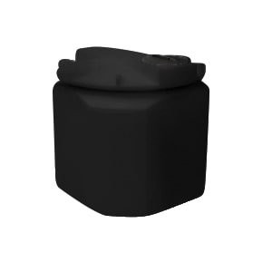
- Reference 100 gallon for very small pump applications. Reference N-44800 100 gallon Norwesco doorway tank with a 0.5 HP transfer pump as the smallest pump-VFD application typical in field service. Single-phase fractional-horsepower motors with VFDs are increasingly common as VFD costs decline; the savings economics work even at small scales for high-duty-cycle applications.
The motor compatibility check is the second engineering decision after VFD sizing. Most existing motors operate acceptably on VFDs; the discipline is in identifying the cases where specific mitigation (inverter-duty motor, shaft grounding, cable filter) is required.
4. The Diurnal Demand Profile and Energy Savings Math
The energy savings from VFD operation depend on the demand profile across the day. A flat demand at full capacity offers little VFD savings; a strongly cyclic demand offers substantial savings:
- The high-cycle daytime profile. A typical industrial water-supply tank pump runs at near-full speed during day shift (8 AM to 6 PM) when production demand is high, dropping to 30-50 percent during evening (6 PM to 10 PM), to 10-20 percent overnight (10 PM to 6 AM), and back up to full speed at shift start. The 24-hour weighted average speed is 50-65 percent.
- The cubic-power-scaled energy calculation. Energy consumption integrates power over time. For a pump at 100 percent speed for 10 hours, 50 percent for 4 hours, 20 percent for 8 hours, and 100 percent for 2 hours: total energy is (1.0 * 10) + (0.125 * 4) + (0.008 * 8) + (1.0 * 2) = 12.6 power-hours. Compared to 24 hours at full speed = 24.0 power-hours. The VFD reduces total energy by 47 percent on this profile.
- The fixed-speed throttling baseline comparison. A fixed-speed pump with a throttle valve or recirculation loop consumes near-full power regardless of flow demand. The VFD savings are calculated against this baseline. For a pump running 24/7 with the diurnal demand profile above, the fixed-speed energy is 24.0 power-hours per day; the VFD energy is 12.6 power-hours per day; the savings are 11.4 power-hours per day per HP of pump rating.
- The economic conversion. At 0.10 dollars per kWh and 0.746 kW per HP, 11.4 HP-hours saved per day equals 8.5 kWh saved per day, equals 0.85 dollars per day, equals 310 dollars per year per HP of rated pump. A 5 HP pump produces approximately 1550 dollars per year of savings. The payback against a 1500-dollar VFD installation is approximately 12 months.
- Demand-charge reduction. Industrial electric service is billed both for energy (kWh) and demand (kW peak in any 15-minute interval). The VFD reduces the peak demand spike at pump start; soft-starting at 0 to 60 Hz over 5-10 seconds eliminates the inrush current that would otherwise drive demand charges. The demand reduction can be worth more than the energy reduction on some rate schedules.
- Time-of-use rate optimization. Some utility tariffs charge higher rates during peak hours. A VFD with timer control or PLC integration can shift pump operation to off-peak hours when total flow demand permits. The savings are additive to the cubic-power-scaled energy savings.
The savings math justifies the VFD investment on most tank-discharge pump applications with cyclic demand. The exceptions are flat-demand applications (continuous full-speed pumping) where the VFD provides minimal energy savings and is justified only by control flexibility or motor protection.
5. Control Strategy and Process Integration
The VFD provides several control strategies that integrate with tank-discharge process requirements:
- Constant pressure control. A pressure transducer downstream of the pump provides feedback to the VFD, which adjusts speed to maintain the target discharge pressure. Constant pressure control is the most common strategy for tank-fed pumps supplying a varying demand network. The control loop is simple and the energy savings track the demand cycle directly.
- Constant flow control. A flow meter downstream provides feedback to maintain target flow rate. Constant flow is appropriate for batch-fill operations or for downstream process steps that require steady flow regardless of pressure. The control loop responds to system curve changes (filter loading, valve adjustments) by adjusting speed to compensate.
- Constant level control on discharge tank. A level transducer on the receiving tank or process vessel feeds back to the pump VFD; the VFD adjusts speed to maintain the target level. Constant level control is appropriate for makeup-water and chemical-feed applications where the receiving vessel level is the controlled variable.
- Soft start and soft stop. Independent of the running control strategy, the VFD ramps from 0 to operating speed over a programmable time (typically 2-30 seconds) at start, and ramps from operating speed to 0 over a similar time at stop. The ramps reduce mechanical shock on pump bearings and seals, reduce water hammer on the discharge piping, and reduce electrical demand spikes.
- Multi-pump alternation and lead-lag operation. A site with two or more pumps on the same discharge can use VFD-coordinated alternation: pump A runs as lead at variable speed, pump B starts as lag when demand exceeds pump A's capacity. The strategy spreads run-time across pumps and provides redundancy. PLC integration is required for the alternation logic.
- Communications integration. Modern VFDs include serial communication (Modbus RTU, Modbus TCP, EtherNet/IP, PROFINET) that enables PLC integration, SCADA monitoring, and remote diagnostic. The communication functionality adds value beyond the basic speed control; it enables real-time efficiency monitoring, predictive maintenance alerts, and operational data logging.
- Reference 2500 gallon for typical mid-size process integration. Reference N-41524 2500 gallon Norwesco as a typical mid-volume installation where the VFD controls a 3-5 HP discharge pump with PLC or SCADA integration. The control architecture decisions apply identically across this size range.
The control strategy selection follows the process requirement: pressure control for distribution networks, flow control for batch fills, level control for makeup applications. The VFD provides the actuator that implements the chosen strategy; the sensors and controller provide the feedback.
6. Installation, Commissioning, and Tuning
The VFD installation and commissioning protocols determine whether the engineered system achieves its design performance:
- VFD enclosure environment. The VFD requires a controlled environment: temperature within the rated range (typically 0-50 C), humidity within rated range (typically below 95 percent non-condensing), and free of conductive dust or corrosive atmospheres. NEMA 1 (indoor general purpose) is the cheapest enclosure; NEMA 4 (outdoor weatherproof) and NEMA 4X (outdoor corrosion-resistant) are required for harsher environments. Tank yard installations often require NEMA 4X.
- Power wiring discipline. Input power conductors are sized per NEC 430 for the VFD input current. Output conductors to the motor are sized per the motor FLA. Conduit is run separately for input and output to avoid PWM noise coupling. Ground conductors include both equipment ground and a dedicated motor frame ground for shaft grounding effectiveness.
- Control wiring discipline. Control signals (analog 4-20 mA, digital start/stop, communication networks) run in separate conduit from power conductors. Shielded cable with grounded shield at one end is the standard for analog signals. The discipline prevents PWM noise from corrupting control signals.
- Parameter setup at commissioning. The VFD has dozens to hundreds of programmable parameters. The commissioning process configures motor nameplate values (HP, voltage, FLA, RPM), control mode (V/Hz, vector, sensorless vector), acceleration and deceleration ramps, current limit, and protection thresholds. Modern drives include guided commissioning routines that walk through the essential parameters.
- Auto-tuning procedure. Modern VFDs include auto-tuning routines that measure motor parameters at startup (winding resistance, magnetizing current, leakage inductance) and configure the vector control loops accordingly. Auto-tune produces better speed accuracy and torque response than manual tuning. The procedure runs in 30-60 seconds at commissioning.
- Operational verification. After commissioning, the system is run through its operational range with measurements: motor current at rated speed and torque (should match nameplate), pump flow at rated speed (should match pump curve), discharge pressure at rated speed (should match system curve), and reduced speed verification (50 percent speed should produce 50 percent flow at 25 percent head per the affinity laws). Deviation from expected indicates configuration or installation issues that require correction.
- Reference small mobile installation for portable VFD use. Reference N-40160 325 gallon Norwesco pickup truck tank as a mobile installation where small portable pumps are common. VFD use on mobile equipment is less common (battery and inverter limitations) but the same principles apply when the application justifies it.
The installation discipline is where commissioning quality is established. A high-quality VFD with poor installation underperforms a basic VFD with excellent installation. The training and supervision that produces good installations is the highest-return investment.
7. Failure Mode Analysis and Maintenance Discipline
Field experience produces a catalog of recurring VFD failure modes and a defined maintenance discipline:
- Capacitor aging and replacement. The DC bus capacitors in the VFD age with time and temperature. After 7-10 years of service the capacitor capacitance has declined and the equivalent series resistance has increased; the bus voltage ripple rises and the drive can trip on bus over-voltage or under-voltage. Capacitor replacement is a defined maintenance event at 7-10 year intervals on continuous-duty drives.
- Cooling fan replacement. The drive cooling fans run continuously when the drive is energized. Bearing wear and bearing seizure are the typical failure mode. Fan failure produces drive over-temperature trips. Replacement at 5-7 year intervals is a defined maintenance event; the fan replacement cost is small (50-200 dollars) compared to the drive replacement cost on overheat damage.
- Filter cleaning and replacement. Drives in dusty environments accumulate dust on the cooling fins and air filters. The accumulation reduces cooling effectiveness and can produce over-temperature trips. Quarterly inspection and cleaning (compressed air, or removal and washing for accessible filters) is the standard discipline.
- Output transistor (IGBT) failure. The output transistors in the VFD fail by short-circuit or open-circuit modes. Short-circuit failures typically trigger drive protective circuits; open-circuit failures produce phase imbalance and motor overheating. IGBT failure at high cycle counts (greater than 10 years on heavily-cycled drives) is a known wear-out mode. Drive replacement is the practical fix.
- Common-mode current bearing damage. As discussed in section 3, bearing currents from PWM common-mode voltages damage motor bearings across years. Without shaft grounding the bearing failure typically develops 3-10 years into service. With shaft grounding the failure is delayed substantially. Bearing condition monitoring (vibration, temperature) catches the development before catastrophic failure.
- Software and parameter drift. Programmable parameters can drift from intended values through accidental operator interaction or memory corruption. Annual review of stored parameters against the commissioning baseline (saved as a reference file) catches drift before it produces operational anomalies. Modern drives include parameter backup to USB or memory card for quick restore.
- Surge and lightning protection. Drives are susceptible to voltage surges from lightning, utility transients, and switching events on adjacent equipment. Surge protection devices on the input power feed protect against these events. Without protection a single lightning event can destroy a drive.
The failure mode catalog supports planned maintenance programming. A site that follows the maintenance discipline experiences VFD service life of 15-20 years; a site that runs drives to failure typically experiences 7-10 year service life with unplanned outages.
8. The VFD Sizing and Installation Conclusion
Variable-speed drive installation on tank-fed pumps is a high-return investment when the demand profile is cyclic. The affinity law math drives the energy savings; the cubic relationship between speed and power produces dramatic reductions on partial-speed operation. The drive sizing follows established rules. The motor compatibility check identifies the cases where specific mitigation is required. The control strategy implements the process requirement. The installation discipline establishes the commissioning quality. The maintenance discipline sustains the drive across its service life.
OneSource Plastics ships polyethylene tanks across the 5-brand catalog (Norwesco, Snyder, Chem-Tainer, Enduraplas, Bushman) sized for tank-discharge pump installations across the size range from doorway to bulk vertical. Tank selection for any specific application is performed by the customer site engineer with reference to flow rates, pump specification, and drive integration. List pricing on each product page; LTL freight to your ZIP via the freight estimator or by phone at 866-418-1777. For related engineering see pump priming and dry-run protection and tank-bottom vs side-mount suction.
Recommended Tanks for This Guide
Live pricing, updated automatically · estimate freight to your ZIP.