Tank Top Fitting Placement Strategy for Polyethylene Bulk Storage: Vent, Fill, Level, Drain, and Vapor-Recovery Layout Engineering That Eliminates Cross-Contamination, Maintenance Conflicts, and Operator Error


The top of a polyethylene bulk tank carries more engineering decisions per square foot than any other surface on the installation. The vent goes somewhere. The fill connection goes somewhere. The level sensor goes somewhere. The drain or sample port goes somewhere. The mixer mount, the manway, the ladder anchor, the heat-trace junction box, and the vapor-recovery connection all compete for the same dome real estate. The default approach — the installer puts each fitting wherever there is open space — produces a tank top that looks finished but operates poorly. The fill splashes into the level sensor. The vent and the fill sit close enough that the vapor blowback contaminates the delivery. The drain is on the wrong side of the tank from the secondary containment slope. The maintenance crew has to climb past three other fittings to reach the one they need to service.
This article walks the engineering of tank top fitting placement for polyethylene bulk storage. The references are the manufacturer technical bulletins from Norwesco, Snyder, Chem-Tainer, Enduraplas, and Bushman on standard top-fitting locations and the engineering envelope around them, ASTM D1998 (polyethylene upright storage tanks), API RP 2350 (overfill prevention guidance), and the ergonomic and access engineering principles from OSHA 29 CFR 1910.23 and 29 CFR 1910.146 (confined space). The objective is the structured layout strategy that places each fitting where it serves its function without conflicting with other fittings or operational workflows.
1. Why Top-Fitting Layout Matters More Than People Think
The fittings on a tank top are not interchangeable. Each one has functional requirements that constrain its location:
- The vent must terminate at the highest point of the tank vapor space to discharge vapor reliably under both fill and drain conditions. A vent installed in a low spot of the dome can be partially submerged during fill and fail to vent until the level drops.
- The fill connection should be located to minimize splash and aeration of the contained liquid, which means it should discharge below the liquid level (via a fill pipe extension) and at a position that promotes circulation rather than localized turbulence.
- The level sensor — capacitive, ultrasonic, hydrostatic, or float — must be positioned to read true level without interference from the fill stream, the mixer wake, or vapor-space turbulence. An ultrasonic sensor positioned over the fill point reads the splash, not the steady level.
- The drain or sample port must be positioned to draw representative liquid at a depth that is neither the surface skim nor the bottom sediment. Surface chemistry can differ materially from bulk chemistry; bottom sediment is unrepresentative of process feed.
- The vapor-recovery connection (when present) must accommodate the directional flow of vapor during fill (vapor displaced out) and during emptying (vapor or air drawn in). The connection point and the line routing must support both directions without trapping condensate or pulling debris.
- The manway must be positioned for human access with adequate clearance from other fittings, structural supports, and any equipment that would block ingress or egress during a confined-space entry.
The conflicts arise when these requirements are not coordinated. The vent and the fill end up in the same quadrant. The level sensor sees the fill splash. The drain port is across the tank from the secondary containment slope. The manway ends up under the mixer bridge. Each of these conflicts is the result of an avoidable layout decision made without the full system view.
2. The Vent Placement Strategy
The vent is the most location-critical fitting on the tank top because it must reliably handle both forward (fill) and reverse (drain) flow without restriction. The engineering rules:
- Locate the vent at the geometric high point of the dome. For a flat-top tank, the vent goes near center; for a domed-top tank, the vent goes at the apex. The location ensures the vent is always above the liquid level under all operating conditions including the highest credible fill point.
- Size the vent for the maximum credible fill rate (forward) and drain rate (reverse). A 2-inch vent supports up to roughly 100-200 GPM of vapor displacement at 6 inches water column pressure differential; a 3-inch vent supports up to 400-600 GPM. The vent must never become the flow restriction during a fast fill or drain operation.
- Equip the vent with a vacuum-breaker and pressure-relief envelope appropriate to the chemistry. For benign chemistry water tanks, a simple gooseneck vent with insect screen suffices. For volatile chemistry, a conservation vent (pressure-vacuum vent) with engineered set points prevents vapor loss without allowing damaging vacuum or overpressure.
- For flammable or hazardous chemistry, equip the vent with a flame arrestor. The arrestor must be positioned where it can be inspected and replaced without confined-space entry. The maintenance access requirement may shift the vent location away from the geometric apex toward an accessible position, with corresponding engineering verification that the alternative location still serves the venting function.
- Maintain vent clearance from any other fitting that could be affected by vapor discharge. The fill connection should not be downwind of the vent during typical operation; the level sensor electronics should not be exposed to corrosive vapor; the operator approaching the manway should not pass directly through the vent discharge plume.
The vent location is the first decision in the tank top layout sequence because every other fitting position is constrained by the vent location.
3. The Fill Connection Placement
The fill connection is the second-most-constrained location decision. The engineering considerations:
- Position the fill connection on the opposite side of the tank from the level sensor. The fill stream creates surface turbulence, splash, and entrained air that interferes with the level reading. Locating these on opposite sides allows the level sensor to read the steady-state surface near the wall while the fill turbulence happens at the far side.
- Use a fill pipe extension that terminates below the liquid level for chemistry that is sensitive to aeration (oxygen-sensitive products, foaming products, vapor-loss products). The fill pipe enters through the top fitting and extends down to within 1-2 feet of the tank bottom. The fill discharge enters subsurface, minimizing splash and air entrainment.
- For chemistry that requires top-fill discharge (level-indicator confirmation, visual inspection during fill), position the fill connection to splash into the bulk volume rather than the wall. Wall splash creates a localized high-velocity jet that can erode the tank wall over time; bulk splash dissipates the energy across a larger volume.
- The fill connection should be reachable from the operator's working position — typically ground level for outdoor tanks, or the platform level for taller installations. The connection geometry (camlock, threaded, flanged) should match the typical delivery hose configuration.
- Provide a fill-line check valve or drain-back arrangement that allows the fill line to drain back to the tank after the delivery rather than holding residual chemistry in the line. The drain-back is particularly important in cold climates where the residual could freeze.
The fill placement should also consider the truck-positioning geometry for bulk delivery. The driver should be able to position the truck for a clean hose connection without backing through the secondary containment, the operator working area, or other equipment.
4. The Level Sensor Placement and Type Selection
The level sensor reads the steady-state liquid level for inventory tracking, alarm setpoints, and refill control. Sensor selection and placement together determine reading accuracy:
- Ultrasonic level sensors mount on the tank top and emit a downward sound pulse, measuring the round-trip time to the liquid surface. They are non-contact (good for hazardous chemistry) but require a clear line-of-sight from the sensor to the surface and are sensitive to vapor density, foam, and surface turbulence. Position the sensor away from the fill stream and the vent.
- Hydrostatic pressure sensors mount at the bottom or partway up the tank wall and read the hydrostatic head of the liquid above the sensor. They give true level regardless of surface turbulence but require a wetted connection that is compatibility-rated for the chemistry.
- Capacitive level sensors use a probe extending into the tank that detects the dielectric change between vapor and liquid. They tolerate foaming and surface turbulence but require careful chemistry-compatibility selection for the probe materials.
- Float-and-tape mechanical level indicators give a visual local reading without electronics. They are simple and reliable but don't connect to any control system unless they include a transmitter option.
- Sight tubes or sight gauges give visual indication via an external transparent column. They require a top and bottom connection on the tank wall and are sensitive to UV, freezing, and chemistry compatibility for the sight material.
The standard practice for bulk-storage tanks is a primary level sensor (typically ultrasonic or hydrostatic) connected to the alarm and control system, plus a secondary visual indicator (sight tube or float-and-tape) that allows operator verification without relying on the electronic system.
5. The Drain, Sample, and Cleanout Port Placement
The drain and sample ports are typically wall fittings rather than top fittings, but their placement coordinates with the top fittings:
- Position the bottom drain on the side that slopes toward the secondary containment. The secondary containment grading typically slopes toward a sump or a containment outlet; the tank drain should align with the slope so any drained fluid follows the engineered drainage path.
- Position the sample port at a representative depth in the tank. The standard convention is roughly 1/3 of the tank height from the bottom, which is below the surface skim and above the bottom sediment. For specific applications (top-skim sampling for separation studies, bottom-sediment sampling for solids-content tracking), the sample port location is application-specific.
- Provide a separate cleanout port if the bottom drain is not large enough for cleanout access. The cleanout is sized to accept a cleaning wand, a vacuum hose, or a personnel access during the cleanout operation. For tanks under 1,500 gallons, the bottom drain may be the only access; for larger tanks, a dedicated cleanout port is standard.
- Provide a manway at a position that does not conflict with the top-fitting layout. The manway typically sits 12-18 inches inboard of the dome edge, where the dome curvature provides the structural envelope for the cutout. The manway should be positioned for direct access from the ladder or platform without requiring the operator to traverse the top-fitting field.
The drain and sample port placement should also consider the lockout-tagout requirements for any maintenance operation. Each port should have an isolation valve that is reachable, lockable, and verifiable from the operator's working position.
6. The Vapor-Recovery and Emergency-Vent Architecture
For chemistry that requires vapor recovery (volatile organic compounds under EPA Method 21, hazardous air pollutants under NESHAPs) or emergency venting (overpressure protection per API 2000 or equivalent), additional fittings are required beyond the standard vent:
- Vapor-recovery connection that ties the tank vapor space to a recovery system. The connection is typically located near the vent (so the vapor space is fully addressed) but routed to a separate piping system that goes to the recovery equipment. The line must include a check valve to prevent reverse flow contaminating the recovery system.
- Emergency vent (separate from the operating vent) sized for the worst-case overpressure scenario. Typical scenarios include external fire (heating the contents to vapor-generation rates exceeding the operating vent capacity), runaway exothermic reaction, or pressurized fill from a malfunctioning delivery system. The emergency vent is sized per API 2000 or equivalent and is typically a frangible disc or weight-loaded relief device.
- Pressure-relief valve for tanks operating with engineered vapor-space pressure. Some chemistry installations maintain a slight inert-gas blanket pressure in the vapor space; the relief valve protects against overpressure if the inert-gas system malfunctions.
- Vacuum relief if the operating envelope includes potential vacuum conditions. Rapid drainage, vapor condensation during temperature drops, or external cooling can pull a vacuum in the vapor space that exceeds the tank's structural envelope. A vacuum-relief valve or properly-sized vacuum-side conservation vent prevents tank collapse.
The vapor-recovery and emergency-vent architecture must be designed before the basic top-fitting layout is finalized, because the fittings for these systems compete for the same dome real estate as the operating fittings.
7. The Tank Selection That Includes Engineered Top-Fitting Patterns
The top-fitting layout is materially easier when the tank manufacturer provides published standard fitting locations with engineered structural envelopes. Norwesco, Snyder, Chem-Tainer, Enduraplas, and Bushman each publish technical drawings showing the standard fitting positions and the design rationale.
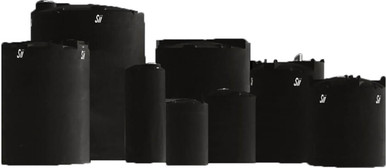
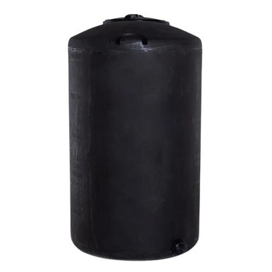
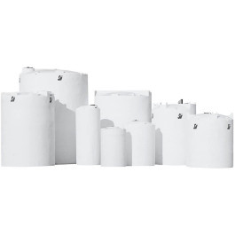
- Vertical bulk tanks with multiple top-fitting bosses pre-engineered for the typical fill, vent, level, and access pattern: reference N-40164 5,000 gallon Norwesco vertical and N-43128 10,000 gallon Norwesco vertical, both with engineered fitting positions documented in the technical drawings.
- Smaller bulk tanks where the layout is constrained by the overall dome dimension: reference N-44800 100 gallon doorway water tank for small-volume installations and N-41867 25 gallon vertical for the laboratory and small-batch end where the layout is necessarily simplified.
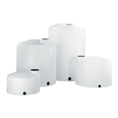
- Cone-bottom tanks where the dome is structurally distinct from the cone: reference N-43852 1,000 gallon 45-degree cone; the cone-bottom design typically integrates the bottom drain into the cone apex, simplifying the wall-fitting layout while leaving the dome top for the standard fitting pattern.
- Double-wall containment tanks for hazardous chemistry where the fitting penetrations must traverse both walls: reference the SII-1006600N42 10,000 gallon XLPE Captor; the double-wall fitting engineering is materially more complex and the manufacturer documentation provides the engineered approach for each fitting type.
The engineering brief should include the full set of operating fittings (vent, fill, level, drain, sample), the safety fittings (emergency vent, pressure relief, vacuum relief), the access fittings (manway, cleanout), and any process-specific fittings (vapor recovery, mixer mount, heat-trace junction). The tank manufacturer specification should be verified against this brief before the order is placed; field-modification of an installed tank to add or move fittings is materially more expensive than specifying the correct pattern at order time.
8. The Layout Drawing as the Engineering Deliverable
The output of the top-fitting placement engineering should be a documented layout drawing that shows:
- The plan view of the tank top with all fittings positioned dimensionally. Each fitting has a unique identifier, a dimensional reference from a fixed datum (typically the centerline of the tank), and a size and type specification.
- The elevation view showing the relationship between the top fittings and any internal features like the fill pipe extension, the level sensor probe depth, or the mixer shaft position.
- The fitting bill-of-materials with manufacturer part numbers, materials of construction, and pressure/temperature ratings.
- The piping connection drawings for each fitting, showing the external piping that ties to each fitting and the routing to the next process equipment or to the disposition point.
- The safety-fitting setpoints and engineering basis, including the emergency vent sizing calculation, the pressure-relief setpoint rationale, and the vacuum-relief sizing.
The layout drawing becomes the master document for the installation, the maintenance reference for field crews, and the regulatory document for SPCC, PSM, or RMP compliance. The drawing should be retained on file at the site and updated whenever a fitting is added, moved, or replaced.
9. The Engineering Discipline Conclusion
The top of a polyethylene bulk tank is a coordinated layout problem with structural, operational, and safety dimensions. Each fitting has a function, a placement constraint, and a relationship to every other fitting. The default approach — install each fitting wherever there is open space — produces a tank top that operates poorly and that is expensive to maintain over its service life. The engineering approach — sequence the layout decisions starting with the vent, then the fill, then the level, then the drain, then the access and safety fittings — produces a tank top that operates as designed for 25+ years.
The cost difference between the two approaches is a few hours of engineering at the design stage. The cost difference in operational outcomes is the decade of maintenance friction, contamination events, and avoidable rework that the unplanned layout creates. The discipline is worth the time every time.
OneSource Plastics ships the polyethylene tank platform that is the foundation of these top-fitting layouts across all 5 brands — Norwesco, Snyder, Chem-Tainer, Enduraplas, Bushman — with technical drawings, fitting specifications, and structural envelope documentation that the application engineer needs to design the layout. List pricing by SKU is on the product page; LTL freight to your ZIP is quoted separately via the freight estimator or by phone at 866-418-1777. For related installation engineering see tank plumbing system design walkthrough and tank overflow port engineering.
Recommended Tanks for This Guide
Live pricing, updated automatically · estimate freight to your ZIP.